The cone crusher main shaft, a critical rotating component connecting the eccentric bushing to the moving cone, performs key functions such as power transmission (driving the moving cone's eccentric rotation), load bearing (withstanding axial and radial loads up to thousands of kilonewtons), eccentric motion guidance (maintaining the moving cone's orbital path), and structural alignment (ensuring concentricity between the moving and fixed cones). It requires exceptional tensile strength, fatigue resistance, and dimensional precision for operation at 500–1500 rpm.
Structurally, it is a stepped, cylindrical or conical forged component consisting of the shaft body (high-strength alloy steel 42CrMo or 35CrNiMo with 100–500 mm diameter and 500–2000 mm length), upper cone mount, eccentric bushing interface, bearing journals, shoulders and keyways, and lubrication channels.
The manufacturing process involves forging (billet heating to 1100–1200°C, open-die forging, precision forging) and heat treatment (quenching and tempering, local surface hardening). Its machining and manufacturing process includes rough machining, precision machining of critical features, lubrication channel drilling, balancing, and surface treatment.
Quality control processes cover material and forging testing (chemical composition analysis, ultrasonic testing), dimensional accuracy checks (using CMM and laser alignment tool), mechanical property testing (hardness and tensile testing), non-destructive testing (MPT and eddy current testing), and functional testing (rotational and load testing). These processes ensure the main shaft achieves the required precision, strength, and reliability to drive the cone crusher's crushing motion in mining and aggregate processing applications
Detailed Introduction to the Cone Crusher Main Shaft Component
1. Function and Role of the Main Shaft
The cone crusher main shaft (also called the spindle) is a critical rotating component at the core of the crusher, connecting the eccentric bushing to the moving cone. Its primary functions include:
Power Transmission: Transmitting torque from the eccentric bushing to the moving cone, driving its eccentric rotation to generate crushing forces.
Load Bearing: Bearing axial and radial loads from the moving cone and crushing process (up to thousands of kilonewtons), transferring these forces to the frame’s bearings.
Eccentric Motion Guidance: Working with the eccentric bushing to maintain the moving cone’s orbital path, ensuring stable crushing gap control and uniform material processing.
Structural Alignment: Maintaining the concentricity between the moving cone and fixed cone, critical for consistent product size and reduced wear on liners.
Given its role in high-speed rotation (500–1500 rpm) and heavy loading, the main shaft requires exceptional tensile strength, fatigue resistance, and dimensional precision.
2. Composition and Structure of the Main Shaft
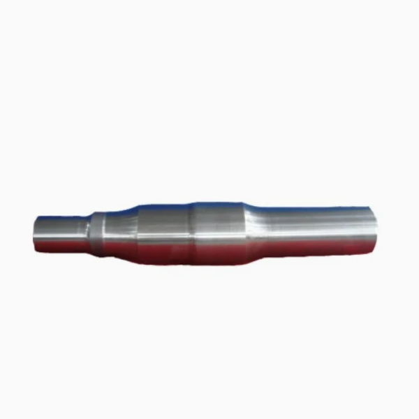
The main shaft is a stepped, cylindrical or conical forged component with the following key features:
Shaft Body: A one-piece forged structure made of high-strength alloy steel (e.g., 42CrMo or 35CrNiMo) with a diameter ranging from 100 mm to 500 mm. Its length varies by crusher size, typically 500–2000 mm.
Upper Cone Mount: A tapered or threaded section at the top for attaching the moving cone, with a precision-machined surface (tolerance IT6) to ensure concentricity.
Eccentric Bushing Interface: A cylindrical middle section with a polished surface (Ra0.8 μm) that fits into the eccentric bushing, often with oil grooves for lubrication.
Bearing Journals: Two or more cylindrical sections (upper and lower) that mate with the frame’s bearings, featuring tight dimensional tolerances (IT5–IT6) and surface roughness (Ra0.4 μm) to minimize friction.
Shoulders and Keyways: Radial shoulders that limit axial movement of bearings or bushings, and keyways for torque transmission between the shaft and moving cone.
Lubrication Channels: Axial and radial drilled holes that deliver lubricant to bearing journals and the eccentric bushing interface, preventing overheating and wear.
3. Forging and Heat Treatment Process
Due to its high load-bearing requirements, the main shaft is manufactured via forging rather than casting to enhance structural integrity:
Material Selection:
High-strength alloy steel (42CrMo) is preferred for its excellent tensile strength (≥1080 MPa), yield strength (≥930 MPa), and impact toughness (≥60 J/cm²), suitable for dynamic load applications.
Forging Process:
Billet Heating: The steel billet is heated to 1100–1200°C in a gas furnace, ensuring uniform temperature distribution to improve plasticity.
Open-Die Forging: The billet is forged into a rough stepped shape using hydraulic presses (1000–5000 tons), with multiple passes to refine the grain structure and eliminate internal defects. Key steps include upsetting (to increase diameter) and drawing (to extend length).
Precision Forging: The rough forging is shaped into the final stepped profile with near-net dimensions, reducing machining allowances to 5–10 mm.
Heat Treatment:
Quenching and Tempering: The forged shaft is heated to 850–880°C, held for 2–4 hours, then quenched in oil to achieve a martensitic structure. Tempering at 550–600°C for 4–6 hours reduces brittleness, resulting in a hardness of HRC 28–35 and optimized toughness.
Local Surface Hardening: Bearing journals and keyways are induction-hardened to a depth of 2–5 mm, achieving HRC 50–55 to enhance wear resistance while maintaining core toughness.
4. Machining and Manufacturing Process
Rough Machining:
The forged blank is mounted on a CNC lathe to machine all outer surfaces (diameters, shoulders, tapers), leaving 1–2 mm finishing allowance. Key dimensions (e.g., journal diameters) are controlled to ±0.1 mm.
Precision Machining of Critical Features:
Bearing Journals: Finish-turned and ground to achieve a dimensional tolerance of IT5 (e.g., φ200H5) and surface roughness Ra0.4 μm, ensuring proper fit with bearings and minimal friction.
Tapered Mount: The upper cone mount is finish-machined to a taper angle tolerance of ±0.05° and surface roughness Ra0.8 μm, ensuring concentricity with the moving cone.
Keyways and Oil Grooves: Milled using CNC machines with positional tolerance (±0.05 mm) and surface finish Ra3.2 μm, preventing stress concentration.
Lubrication Channel Drilling:
Axial and radial oil holes (φ5–φ15 mm) are drilled using CNC deep-hole drilling machines, with positional accuracy (±0.2 mm) to ensure unobstructed lubricant flow. Hole ends are deburred to avoid oil flow disruption.
Balancing:
The shaft undergoes dynamic balancing on a balancing machine at 500–1000 rpm, with residual unbalance limited to ≤5 g·mm/kg to reduce vibration and bearing wear.
Surface Treatment:
Bearing journals are polished to Ra0.2 μm to reduce friction and improve bearing life.
Non-bearing surfaces are coated with anti-rust paint or zinc plating (5–8 μm) to resist corrosion during storage and operation.
5. Quality Control Processes
Material and Forging Testing:
Chemical composition analysis (spectrometry) confirms compliance with 42CrMo standards (C 0.38–0.45%, Cr 0.9–1.2%, Mo 0.15–0.25%).
Forging quality is inspected via ultrasonic testing (UT) to detect internal defects (e.g., cracks, inclusions) with size limits ≤φ2 mm.
Dimensional Accuracy Checks:
A coordinate measuring machine (CMM) verifies all critical dimensions: journal diameters, taper angles, keyway positions, and oil hole locations.
Roundness and straightness of the shaft are measured using a laser alignment tool, with tolerance ≤0.01 mm/m.
Mechanical Property Testing:
Hardness testing (Rockwell) ensures bearing journals have HRC 50–55 and the core has HRC 28–35.
Tensile testing on forged samples confirms tensile strength ≥1080 MPa and elongation ≥12%.
Non-Destructive Testing (NDT):
Magnetic particle testing (MPT) detects surface cracks in keyways, shoulders, and journals, with any defect >0.2 mm in length rejected.
Eddy current testing checks for subsurface defects in hardened journal surfaces.
Functional Testing:
Rotational testing: The shaft is mounted in a test fixture and rotated at maximum speed (1500 rpm) for 2 hours, with vibration monitored to ensure levels ≤0.1 mm/s.
Load testing: A simulated axial load (120% of rated load) is applied for 1 hour, with post-test inspection showing no deformation (e.g., journal roundness change ≤0.005 mm).
Through these manufacturing and quality control processes, the main shaft achieves the precision, strength, and reliability required to drive the cone crusher’s crushing motion, ensuring efficient and long-term operation in mining and aggregate processing applications