• mobile cone crusher
  • video

mobile cone crusher

  • SLM
  • 中国
  • 3 months
  • 100 sets/ year
The mobile cone crusher integrates a cone crusher, feeding/screening devices, conveyors, and a mobile chassis, designed for on-site crushing of medium to hard materials (granite, basalt, etc.) with high mobility. It features a mobile chassis (frame, axles/wheels, hydraulic jacks), cone crusher unit (crushing chamber, eccentric shaft, motor), feeding/screening system, conveyors, and hydraulic/electrical controls, with a processing capacity of 50–500 t/h.​ Manufacturing involves welding and machining the Q355B steel chassis, casting (high-chromium cast iron for cones, ZG35CrMo for eccentric shafts) with heat treatment, and assembling components. Quality control includes material testing, dimensional inspection, performance tests (no-load/load/mobility), and safety checks. Installation requires site preparation, transportation, leveling, and commissioning. Widely used in mining, road construction, and infrastructure, it delivers uniform, high-cubicity aggregates efficiently
Detailed Introduction to Mobile Cone Crusher
1. Overview and Application of Mobile Cone Crusher
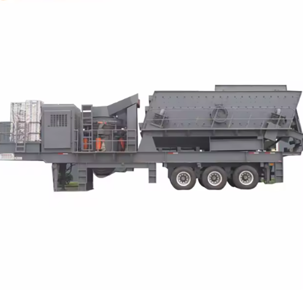
Mobile cone crusher is a integrated crushing equipment that combines a cone crusher, feeding device, screening device, conveyor belt, and mobile chassis. It is designed for on-site crushing of medium to hard materials, such as granite, basalt, iron ore, and concrete aggregates. Its biggest advantage is mobility, which allows it to move flexibly between construction sites, reducing material transportation costs and improving crushing efficiency.
This equipment is widely used in mining, road construction, urban demolition, and infrastructure projects. It can perform secondary or tertiary crushing, producing aggregates with uniform particle size and high cubicity, which can be directly used in construction or further processed. The processing capacity of mobile cone crushers ranges from 50 to 500 tons per hour, meeting the needs of different scales of projects.
2. Composition and Structure of Mobile Cone Crusher
Mobile cone crusher is a complex system composed of multiple components, each with a specific function to ensure the smooth progress of the crushing process:
2.1 Mobile Chassis
  • Frame: A welded structure made of high-strength steel (Q355B) with a thickness of 16–30 mm. It serves as the base for installing all other components and is designed with sufficient rigidity to withstand the weight and vibration of the equipment.

  • Axles and Wheels: Equipped with 2–6 axles (depending on the model) and heavy-duty tires (load capacity 10–20 tons each) or crawler tracks. Tires are suitable for road transportation, while crawlers are used for rough terrain with poor ground conditions.

  • Hydraulic Jacks: 4–6 hydraulic jacks installed at the four corners of the chassis for leveling the equipment during operation, ensuring stability. The lifting height is 100–300 mm.

2.2 Cone Crusher Unit
  • Crushing Chamber: Consists of a fixed cone (concave) and a moving cone, both lined with wear-resistant liners (high-chromium cast iron Cr20). The fixed cone is installed on the frame, and the moving cone is driven by an eccentric shaft to perform periodic swing, crushing materials through extrusion and impact.

  • Eccentric Shaft: A cast steel (ZG35CrMo) component with an eccentricity of 8–25 mm, which is the core part that drives the moving cone to swing. It is connected to the motor through a bevel gear transmission.

  • Main Motor: A three-phase asynchronous motor (75–250 kW) that provides power for the cone crusher. It is installed on the chassis and connected to the eccentric shaft via a V-belt or coupling.

2.3 Feeding and Screening System
  • Feeding Hopper: A welded steel structure with a capacity of 1–5 cubic meters, equipped with a vibrating feeder to control the feeding speed. The hopper is lined with a wear-resistant plate to reduce wear.

  • Vibrating Screen: A circular or linear vibrating screen installed at the discharge end of the cone crusher. It screens the crushed materials into different particle sizes (e.g., 0–5 mm, 5–10 mm, 10–20 mm). The screen mesh is made of high manganese steel (ZGMn13) or polyurethane.

  • Return Conveyor: A belt conveyor that transports the oversize materials (larger than the required particle size) from the vibrating screen back to the cone crusher for re-crushing.

2.4 Conveyor System
  • Main Conveyor: Transports the crushed materials from the cone crusher to the vibrating screen. It is composed of a conveyor belt (rubber material, thickness 5–10 mm), rollers, and a driving device.

  • Side Conveyors: 2–3 side conveyors that transport the screened materials of different particle sizes to separate stockpiles. The length of the conveyors is 5–10 meters, and the conveying speed is 1–2 m/s.

2.5 Hydraulic and Electrical Systems
  • Hydraulic System: Includes hydraulic pumps, cylinders, and control valves. It is used for adjusting the discharge port of the cone crusher, lifting the feeding hopper, and controlling the movement of the crawler tracks (for crawler-type mobile crushers). The working pressure is 16–25 MPa.

  • Electrical Control System: A PLC control cabinet with a touch screen, which can realize automatic control of the equipment, such as starting and stopping in sequence, overload protection, and fault alarm. It is also equipped with a remote control device for convenient operation.

3. Manufacturing Processes of Mobile Cone Crusher
3.1 Mobile Chassis Frame (Q355B Steel)
  • Cutting and Blanking: The steel plates are cut into the required sizes using a CNC plasma cutting machine, with a dimensional tolerance of ±1 mm.

  • Welding: The frame components are welded using submerged arc welding, with a weld seam height of 8–15 mm. After welding, the frame is subjected to stress relief annealing at 600–650°C to eliminate welding stress.

  • Machining: The mounting surfaces for the cone crusher, motor, and hydraulic system are machined using a CNC milling machine, ensuring flatness ≤0.1 mm/m and surface roughness Ra3.2 μm.

3.2 Cone Crusher Components
  • Fixed Cone and Moving Cone (High-Chromium Cast Iron Cr20):

  • Pattern Making: Sand patterns are made according to the design drawings, with a shrinkage allowance of 1.5–2.0%.

  • Molding and Pouring: Resin-bonded sand molds are used, and molten iron (temperature 1450–1500°C) is poured into the molds.

  • Heat Treatment: The castings are subjected to solution annealing at 950–1000°C and tempering at 250–300°C to achieve a hardness of HRC 55–60.

  • Eccentric Shaft (ZG35CrMo Cast Steel):

  • Casting: The eccentric shaft is cast using a sand mold, and after casting, it is normalized at 880–920°C and tempered at 550–600°C to obtain a hardness of HB 220–260.

  • Machining: The outer circle and eccentric bore are machined using a CNC lathe, with a dimensional tolerance of IT7.

3.3 Vibrating Screen (High Manganese Steel ZGMn13)
  • Screen Frame: Welded using Q355B steel, then stress-relieved. The screen surface is made of high manganese steel plates, which are cut and punched to form the screen mesh with a hole size tolerance of ±0.5 mm.

  • Vibration Motor Mounting: The mounting plate for the vibration motor is machined to ensure perpendicularity with the screen frame, with a tolerance of ±0.05 mm.

4. Processing Processes
4.1 Cone Crusher Assembly
  • Eccentric Shaft Installation: The eccentric shaft is installed in the main frame of the cone crusher, and the bevel gears are assembled with a meshing clearance of 0.1–0.3 mm.

  • Moving Cone and Fixed Cone Installation: The moving cone is installed on the eccentric shaft, and the fixed cone is fixed on the frame. The gap between the moving cone and fixed cone (discharge port) is adjusted to the design value (5–30 mm) using hydraulic cylinders.

4.2 Mobile Chassis Assembly
  • Axle and Wheel Installation: The axles are welded or bolted to the chassis frame, and the wheels are installed with bearings, ensuring that the wheel axes are parallel to each other.

  • Hydraulic Jack Installation: The hydraulic jacks are fixed to the chassis, and the hydraulic pipes are connected, with pressure testing at 1.5 times the working pressure to ensure no leakage.

4.3 Electrical System Wiring
  • Wire Routing: The electrical wires are laid in cable trays, with proper insulation and protection. The connections between the motor, control cabinet, and sensors are made using terminal blocks, ensuring reliable contact.

  • Programming: The PLC control system is programmed according to the operation logic, including start-up sequence, overload protection parameters, and fault handling procedures.

5. Quality Control Processes
  • Material Inspection:

  • The chemical composition of steel plates, castings, and wear-resistant materials is tested using a spectrometer to ensure compliance with standards.

  • The mechanical properties (tensile strength, impact toughness) of key components are tested through sampling.

  • Dimensional Inspection:

  • The frame, cone crusher components, and conveyor belts are inspected using calipers, micrometers, and CMM (Coordinate Measuring Machine) to ensure dimensional accuracy.

  • The parallelism and perpendicularity of key mounting surfaces are checked using a level and square ruler.

  • Performance Testing:

  • No-load Test: The equipment is run without load for 2 hours to check the rotation of the cone crusher, vibrating screen, and conveyors, ensuring no abnormal noise or overheating (bearing temperature ≤70°C).

  • Load Test: The equipment is tested with materials (e.g., granite) for 8 hours, checking the processing capacity, product particle size distribution, and stability of the hydraulic and electrical systems.

  • Mobility Test: For tire-type mobile crushers, road tests are conducted to check the driving performance and braking system. For crawler-type, tests on rough terrain are performed to verify the climbing ability and stability.

  • Safety Inspection:

  • The safety guards (e.g., for conveyor belts, rotating parts) are checked to ensure they are firmly installed and meet safety standards.

  • The emergency stop button is tested to ensure it can stop all equipment immediately when pressed.

6. Installation Process
  • Site Preparation: The installation site should be flat and solid, with a bearing capacity of ≥200 kPa. If necessary, a concrete foundation or steel platform can be built.

  • Equipment Transportation: The mobile cone crusher is transported to the site using a trailer. For crawler-type, it can move to the site by itself.

  • Leveling: The hydraulic jacks are extended to lift the chassis, and shims are placed under the jacks to level the equipment (levelness ≤0.5 mm/m).

  • Connecting Auxiliary Facilities: The power cable is connected to the control cabinet, and the water pipe (if needed for dust suppression) is connected to the water tank.

  • Commissioning:

  • Check all connections (bolts, hydraulic pipes, electrical wires) to ensure they are tight and correct.

  • Run the equipment in no-load mode for 30 minutes, adjusting the belt tension and vibration amplitude of the vibrating screen.

  • Perform a load test with a small amount of materials, adjusting the feeding speed and discharge port size to achieve the desired product particle size.

  • After the test runs are successful, the equipment is ready for formal operation.

Mobile cone crusher, with its flexible mobility and efficient crushing performance, has become an important equipment in modern engineering construction. Through strict manufacturing processes, precise processing, and comprehensive quality control, it can meet the harsh working conditions of various construction sites and provide high-quality aggregates for projects


Related Products

Get the latest price? We will reply as soon as possible (within 12 hours)