| SHILONG SIMENS圆锥破碎机 |
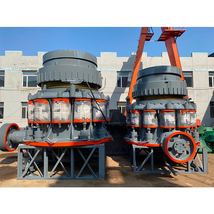
型号及规格
Model | 腔型
Cavity | 给矿口尺寸
Feeding Size
(mm) | 最小
排矿口
min
Discharge
(mm) | 电机功率
Power
(KW) | 设备重量
Weight
(t) | 排矿口尺寸
Discharge
Size
(mm) | 产量
Yield
(t/h) |
闭口边
Closed Size | 开口边Open Size |
| PYS-B0607 | 标准 | 细型 | 57 | 72 | 6 | 30 | 7.21 | 6-25 | 10-52 |
| PYS-B0609 | 粗型 | 83 | 95 | 9 | 9-31 | 12-55 |
| PYS-D0603 | 短头 | 细型 | 19 | 35 | 3 | 7.56 | 3-13 | 6-40 |
| PYS-D0605 | 粗型 | 38 | 51 | 5 | 5-16 | 10-45 |
| PYS-B0910 | 标准 | 细型 | 83 | 102 | 9 | 75 | 14.3 | 9-22 | 40-95 |
| PYS-B0917 | 粗型 | 159 | 175 | 13 | 13-38 | 50-160 |
| PYS-B0918 | 特粗型 | 163 | 178 | 25 | 25-64 | 110-170 |
| PYS-D0904 | 短头 | 细型 | 13 | 41 | 3 | 14.64 | 3-13 | 25-90 |
| PYS-D0906 | 中型 | 33 | 60 | 3 | 3-16 | 25-95 |
| PYS-D0907 | 粗型 | 51 | 76 | 6 | 6-19 | 60-125 |
| PYS-B1313 | 标准 | 细型 | 109 | 137 | 13 | 160 | 24.5 | 13-31 | 105-180 |
| PYS-B1321 | 中型 | 188 | 210 | 16 | 16-38 | 130-250 |
| PYS-B1324 | 粗型 | 216 | 241 | 19 | 19-51 | 170-350 |
| PYS-B1325 | 特粗型 | 238 | 259 | 25 | 25-51 | 235-360 |
| PYS-D1306 | 短头 | 细型 | 29 | 64 | 5 | 25 | 5-16 | 50-160 |
| PYS-D1308 | 中型 | 54 | 89 | 6 | 6-16 | 75-160 |
| PYS-D1310 | 粗型 | 70 | 105 | 8 | 8-25 | 100-215 |
| PYS-D1313 | 特粗型 | 98 | 133 | 16 | 16-25 | 180-225 |
| PYS-B1620 | 标准 | 细型 | 188 | 209 | 16 | 240 | 51.25 | 16-38 | 180-325 |
| PYS-B1624 | 中型 | 213 | 241 | 22 | 22-51 | 260-420 |
| PYS-B1626 | 粗型 | 241 | 269 | 25 | 25-64 | 300-635 |
| PYS-D1636 | 特粗型 | 331 | 368 | 38 | 38-64 | 430-630 |
| PYS-D1607 | 短头 | 细型 | 35 | 70 | 5 | 52.51 | 5-13 | 100-210 |
| PYS-D1608 | 中型 | 54 | 89 | 6 | 6-19 | 135-310 |
| PYS-D1613 | 粗型 | 98 | 133 | 10 | 10-25 | 190-335 |
| PYS-D1614 | 特粗型 | 117 | 158 | 13 | 13-25 | 250-335 |
| PYS-B2127 | 标准 | 细型 | 253 | 278 | 19 | 400 | 108 | 19-38 | 540-800 |
| PYS-B2133 | 中型 | 303 | 334 | 25 | 25-51 | 670-1100 |
| PYS-B2136 | 粗型 | 334 | 369 | 31 | 31-64 | 850-1400 |
| PYS-B2146 | 特粗型 | 425 | 460 | 38 | 38-64 | 970-1400 |
| PYS-D2110 | 短头 | 细型 | 51 | 105 | 6 | 110 | 6-16 | 300-450 |
| PYS-D2113 | 中型 | 95 | 133 | 10 | 10-19 | 390-560 |
| PYS-D2117 | 粗型 | 127 | 178 | 13 | 13-25 | 480-660 |
| PYS-D2120 | 特粗型 | 152 | 203 | 16 | 16-25 | 560-720 |
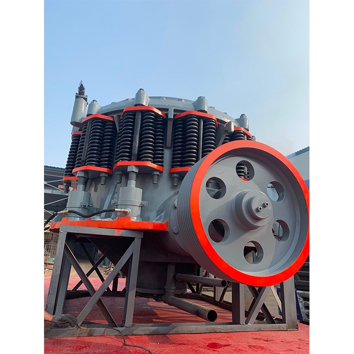
Detailed Introduction to Cone Crusher
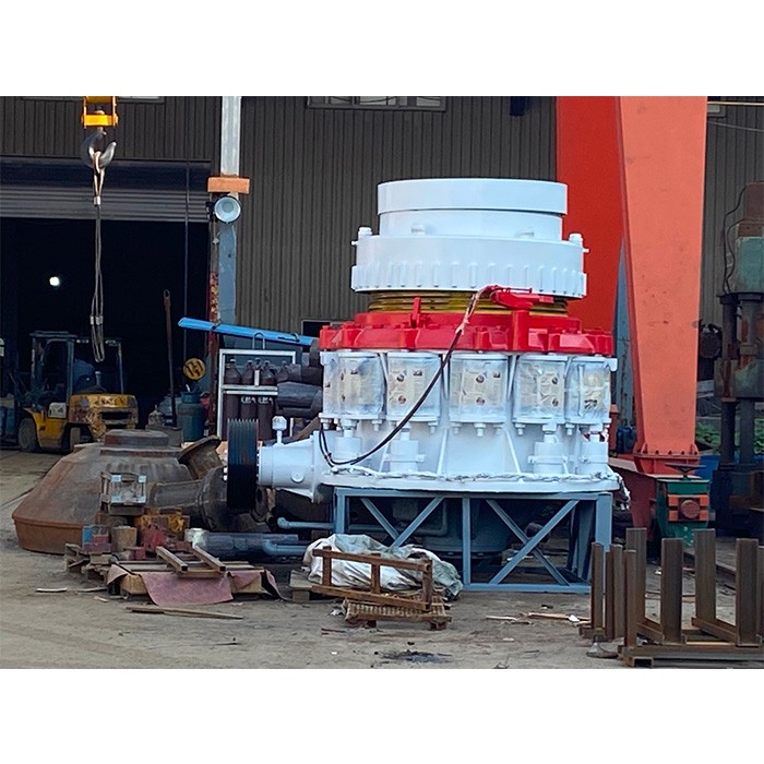
1. Overview and Working Principle of Cone Crusher
Cone crusher is a key equipment for medium and fine crushing of hard materials (compressive strength ≤300MPa), widely used in mining, construction, metallurgy, and chemical industries. Its working principle is based on the "crushing cavity" formed by the moving cone and fixed cone: the motor drives the eccentric shaft sleeve to rotate through the transmission system, making the moving cone perform periodic swing motion. Materials are continuously squeezed, bent, and impacted between the moving cone and fixed cone, gradually crushed into small particles, and discharged through the discharge port when reaching the required size.
Compared with other crushers, it has the advantages of high crushing efficiency, uniform product particle size, and strong adaptability to hard materials, making it suitable for crushing ores (iron ore, copper ore), rocks (granite, basalt), and aggregates.
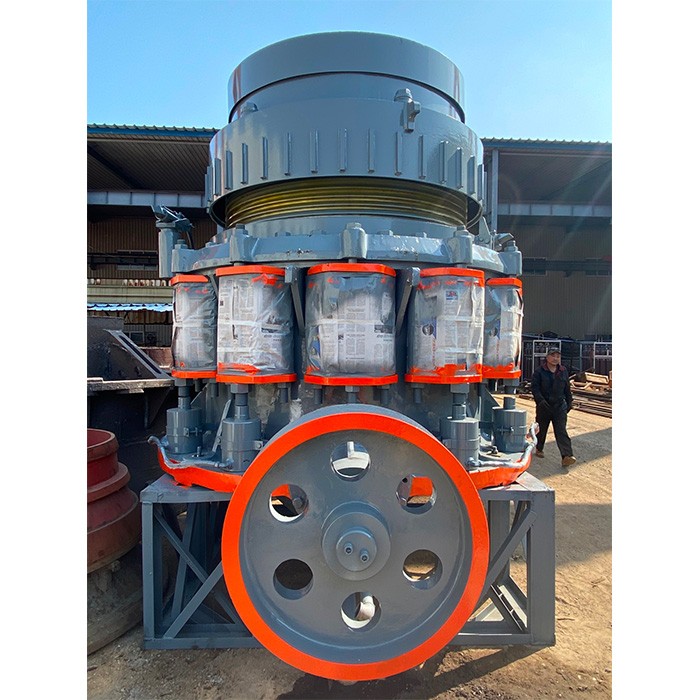
2. Composition and Structure of Cone Crusher
Cone crusher is mainly composed of the following core components, which work together to complete the crushing process:
2.1 Main Frame Assembly
Upper Frame: A cast steel (ZG270-500) structure with a cylindrical shape, supporting the fixed cone and adjustment mechanism. Its inner wall is processed with a tapered surface to match the fixed cone liner, and the top is connected to the feeding hopper. The thickness of the frame wall is 30-80mm, and radial reinforcing ribs are designed to resist the crushing force.
Lower Frame: A heavy-duty cast steel (ZG35CrMo) base that bears the weight of the entire equipment and the reaction force during crushing. It is fixed on the foundation with anchor bolts and internally accommodates the eccentric shaft sleeve, main shaft bearing, and lubrication system.
2.2 Crushing Assembly
Moving Cone: The core working part, consisting of a cone body and a wear-resistant liner. The cone body is forged from 42CrMo alloy steel, with a spherical bottom that fits with the spherical bearing of the main shaft to ensure flexible swing. The liner is made of high-chromium cast iron (Cr20) or manganese steel (ZGMn13), which is fixed on the cone body by pouring zinc alloy to ensure close contact.
Fixed Cone (Concave): An annular liner installed on the inner wall of the upper frame, usually composed of 3-6 segments for easy replacement. The material is the same as the moving cone liner, and its inner surface is designed with a specific taper (15°-30°) and tooth shape to form a crushing cavity with the moving cone.
2.3 Transmission Assembly
Eccentric Shaft Sleeve: A cast steel (ZG35CrMo) sleeve with an eccentric bore, which is the key part to drive the moving cone to swing. Its eccentricity (5-20mm) determines the swing amplitude of the moving cone, and the outer surface is equipped with a large bevel gear.
Main Shaft: A forged alloy steel (40CrNiMoA) shaft, with the upper end connected to the moving cone and the lower end inserted into the eccentric bore of the eccentric shaft sleeve. It transmits the torque and crushing force, with a diameter of 80-300mm depending on the model.
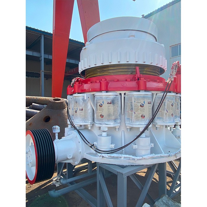
2.4 Adjustment and Safety System
Discharge Port Adjustment Device: Composed of an adjustment ring, support ring, and hydraulic cylinder (for hydraulic cone crushers) or a handwheel (for spring cone crushers). Rotating the adjustment ring can change the height of the fixed cone, thereby adjusting the discharge port size (5-50mm).
Safety Device: Spring group (for spring cone crushers) or hydraulic cylinder (for hydraulic cone crushers). When uncrushable materials enter the crushing cavity, the safety device is triggered to expand the discharge port, discharge the foreign matter, and then reset automatically to protect the equipment.
2.5 Lubrication and Dustproof System
Lubrication System: An independent thin oil lubrication system with oil pump, cooler, and filter, which delivers lubricating oil (ISO VG 46) to the main shaft bearing, eccentric shaft sleeve, and gear pair to reduce friction and control temperature (≤60℃).
3. Casting Processes for Key Components
3.1 Frame (ZG270-500 and ZG35CrMo)
The raw materials are melted in an induction furnace, and the temperature is controlled at 1520-1560℃. For ZG35CrMo, chromium and molybdenum are added to adjust the chemical composition (Cr: 0.8-1.2%, Mo: 0.2-0.3%).
Heat Treatment: After casting, normalization (880-920℃, air cooling) is performed to refine the grain, then tempering (550-600℃) to eliminate internal stress, and the hardness is controlled at HB 180-220.
3.2 Eccentric Shaft Sleeve (ZG35CrMo)
Pouring and Heat Treatment: The molten steel is poured at 1500-1540℃. After casting, quenching (850℃, oil cooling) and tempering (580℃) are carried out to obtain a tempered sorbite structure, with hardness HB 220-260 and tensile strength ≥785MPa.
3.3 Moving Cone Body (42CrMo Forging)
Forging: Open-die forging is used, with multiple upsetting and drawing processes to form the conical shape and spherical bottom, ensuring that the metal grain flow is consistent with the stress direction.
Heat Treatment: Quenching (840℃, water cooling) and tempering (560℃) are performed to achieve a hardness of HRC 28-32, tensile strength ≥900MPa, and good toughness.
4. Machining Processes
4.1 Frame Machining
Rough Machining: Use CNC milling machine to process the flange surface and reinforcing ribs, removing the casting skin and leaving a machining allowance of 2-3mm. Boring machine is used to process the bearing seat, with dimensional tolerance IT8.
4.2 Eccentric Shaft Sleeve Machining
Grinding: Grind the outer circle and eccentric bore to dimensional tolerance IT6, surface roughness Ra0.8μm. Process the keyway and gear mounting surface, ensuring the perpendicularity between the gear surface and the axis ≤0.02mm/100mm.
4.3 Main Shaft Machining
Turning: Process the outer circle, step, and end face on a CNC lathe, leaving a grinding allowance of 0.3-0.5mm.
4.4 Moving Cone and Fixed Cone Liners Machining
5. Quality Control Processes
Use a spectrometer to analyze the chemical composition of cast and forged parts, ensuring they meet the requirements of the material standard (e.g., ZG35CrMo: C 0.32-0.40%, Mn 0.5-0.8%).
Use coordinate measuring machine (CMM) to inspect key dimensions, such as the eccentricity of the eccentric shaft sleeve, the taper of the moving cone, and the position of the bolt holes.
Empty Load Test: Run the equipment without load for 2-4 hours, check the rotation of the rotor, the temperature of the bearing (≤70℃), and whether there is abnormal noise.
Load Test: Crush standard materials (e.g., granite) for 8-12 hours, check the production capacity, discharge particle size distribution, and wear of the liners. The product particle size should meet the design requirements (e.g., 5-20mm), and the liners should have uniform wear.
Simulate the entry of uncrushable materials (e.g., iron blocks) to test the response of the safety device, ensuring it can expand the discharge port in time (≤2 seconds) and reset accurately after discharging the foreign matter.
Through strict manufacturing processes and quality control, cone crushers can achieve stable and efficient operation, meeting the crushing needs of various industries for hard materials