• VSI Sand Making Crusher
  • video

VSI Sand Making Crusher

  • SLM
  • 中国
  • 3 months
  • 100 sets/ year
The VSI Sand Making Crusher is a high-efficiency device for producing high-quality artificial sand and shaping aggregates, utilizing "stone-on-stone" or "stone-on-iron" impact crushing with a high-speed rotor (2800–3500 rpm). It is widely used in construction and infrastructure projects, processing granite, limestone, etc., to produce sand with excellent grain shape (cubicity ≥90%, needle-like content ≤10%) and adjustable fineness modulus (2.6–3.0).​ Structurally, it includes a main body (upper cover, crushing chamber, lower frame), rotor assembly (rotor disk, throwing heads, main shaft), feeding system, drive system, and lubrication/cooling system. Key components like the 42CrMo rotor disk and Cr20–25 throwing heads undergo precision forging/casting, with heat treatment to ensure strength and wear resistance.​ Manufacturing involves forging (rotor disk, main shaft), casting (throwing heads), and CNC machining for tight tolerances. Quality control includes material testing, dimensional inspection (CMM), NDT (UT, MPT), and performance tests (dynamic balancing, load runs).​ Installation requires a stable foundation, precise alignment of components, and system commissioning. This crusher ensures efficient production of high-quality sand for modern construction needs.
Detailed Introduction to VSI Sand Making Crusher
1. Overview and Application of VSI Sand Making Crusher
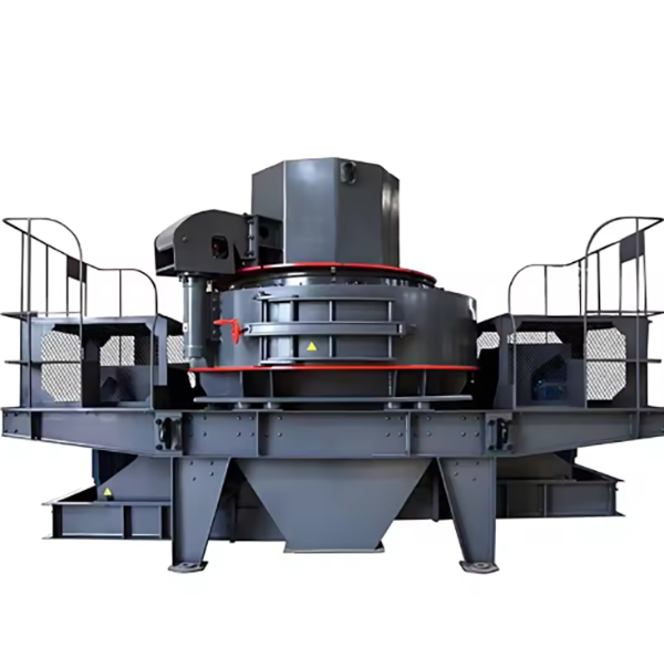
VSI (Vertical Shaft Impact) sand making crusher is a high-efficiency equipment designed for producing high-quality artificial sand and shaping aggregates. It utilizes the principle of "stone-on-stone" or "stone-on-iron" impact crushing: materials are accelerated by a high-speed rotating rotor (speed 2800–3500 rpm) and thrown against the crushing chamber liner or other materials, achieving crushing through impact, friction, and shearing.
This crusher is widely used in construction, highway, railway, and water conservancy projects, suitable for processing materials such as granite, limestone, river pebbles, and ore. It produces sand with excellent grain shape (high cubicity, low needle-like content ≤10%) and adjustable fineness modulus (2.6–3.0), meeting national standards for construction sand.
2. Composition and Structure of VSI Sand Making Crusher
VSI sand making crusher consists of core components working in coordination to ensure efficient sand production:
2.1 Main Body Assembly
  • Upper Cover: A cast steel (ZG270-500) or welded steel structure (Q355B) forming the top of the crushing chamber. It is equipped with a feeding port and a material guide device, with reinforcing ribs to withstand impact forces.

  • Crushing Chamber: A cylindrical cavity lined with wear-resistant plates (high-chromium cast iron Cr20). There are two types of chambers: "stone-on-stone" (for hard materials) with a vortex-shaped liner, and "stone-on-iron" (for medium-hard materials) with a 反击板 (impact plate).

  • Lower Frame: A heavy-duty cast steel (ZG35CrMo) base supporting the rotor and motor, fixed to the foundation with anchor bolts. It contains the discharge port and a access door for maintenance.

2.2 Rotor Assembly
  • Rotor Disk: A forged steel (42CrMo) disk with a thickness of 50–100 mm, mounted on the main shaft. It has evenly distributed material throwing heads (6–12 pieces) and flow channels for material acceleration.

  • Throwing Heads: Wear-resistant components made of high-chromium cast iron (Cr20–25) or cemented carbide, bolted to the rotor disk. Their shape (curved or straight) determines material throwing speed and angle.

  • Main Shaft: A forged alloy steel (40CrNiMoA) shaft with a diameter of 80–180 mm, connecting the rotor disk to the motor. It is supported by high-precision angular contact ball bearings at both ends to withstand high-speed rotation.

2.3 Feeding and Distribution System
  • Feeding Hopper: A welded steel structure with a wear-resistant liner, guiding materials into the crusher. It is equipped with a vibrating feeder or a metering device to control feeding rate.

  • Material Distributor: A cone-shaped component inside the upper cover, distributing materials into two parts: one part enters the rotor for acceleration, and the other falls into the crushing chamber for "stone-on-stone" crushing.

2.4 Drive System
  • Motor: A high-speed asynchronous motor (75–315 kW) with a frequency converter for speed adjustment. It is connected to the main shaft via a coupling or V-belt drive.

  • Pulley/Coupling: For V-belt drive, a large pulley on the main shaft and a small pulley on the motor ensure a transmission ratio of 1:1.2–1:1.5. Couplings (e.g., elastic pin coupling) are used for direct drive to reduce energy loss.

2.5 Lubrication and Cooling System
  • Lubrication System: An automatic grease lubrication pump or thin oil lubrication system that delivers lubricant to bearings. The thin oil system uses ISO VG 32 oil, with a flow rate of 2–5 L/min.

  • Cooling Device: A water-cooled or air-cooled radiator for the lubrication system, maintaining oil temperature below 60°C during high-speed operation.

3. Manufacturing Processes of VSI Sand Making Crusher
3.1 Rotor Disk (42CrMo Forging)
  • Billet Heating: Steel billets are heated to 1150–1200°C in a gas furnace to ensure plasticity.

  • Forging: Open-die forging is used, with upsetting and drawing processes to form the disk shape. The grain flow is aligned along the radial direction to enhance impact resistance.

  • Heat Treatment: Quenching at 840–860°C (oil-cooled) and tempering at 560–600°C to achieve hardness HRC 28–32 and tensile strength ≥900 MPa.

3.2 Throwing Heads (High-Chromium Cast Iron Cr20–25)
  • Pattern Making: Foam patterns are made with a shrinkage allowance of 1.5–2.0%, considering the complex shape of the throwing heads.

  • Molding: Resin-bonded sand molds are used, with the cavity coated with a zirconium-based refractory coating to improve surface quality.

  • Melting and Pouring:

  • Raw materials are melted in an induction furnace at 1450–1500°C, with chromium and molybdenum added to achieve the chemical composition (C 3.0–3.5%, Cr 20–25%).

  • Molten iron is poured into the mold at 1400–1450°C, with a controlled pouring speed to avoid inclusions.

  • Heat Treatment: Solution annealing at 980–1020°C (air-cooled) and tempering at 280–320°C to achieve hardness HRC 60–65 and good toughness.

3.3 Main Shaft (40CrNiMoA Forging)
  • Forging: Billet heating to 1100–1150°C, followed by precision forging to form the shaft with steps and keyways.

  • Heat Treatment: Quenching at 820–840°C (water-cooled) and tempering at 500–550°C to achieve hardness HRC 28–32, yield strength ≥835 MPa.

4. Processing Processes
4.1 Rotor Disk Machining
  • Rough Machining: CNC milling machine processes the outer circle, end face, and mounting holes for throwing heads, leaving a 1–2 mm allowance.

  • Precision Machining: Grinding the end face to flatness ≤0.05 mm/m and surface roughness Ra1.6 μm. Drilling and tapping the bolt holes (M16–M24) with thread tolerance 6H.

4.2 Main Shaft Machining
  • Turning: CNC lathe processes the outer circle, steps, and keyways, leaving a 0.3–0.5 mm grinding allowance.

  • Grinding: Journal surfaces are ground to IT5 tolerance and surface roughness Ra0.4 μm, ensuring coaxiality ≤0.01 mm.

4.3 Crushing Chamber Liner (High-Chromium Cast Iron)
  • Milling: CNC machining center shapes the inner surface of the liner to match the vortex or impact plate design, with surface roughness Ra3.2 μm.

  • Drilling: Mounting holes are drilled to ensure accurate positioning on the upper cover or lower frame.

4.4 Frame and Cover Machining
  • Welding and Stress Relief: Welded components (upper cover, lower frame) are annealed at 600–650°C to eliminate welding stress.

  • Milling: CNC milling machine processes the mating surfaces of the upper cover and lower frame, ensuring flatness ≤0.1 mm/m for tight sealing.

5. Quality Control Processes
  • Material Testing:

  • Spectrometric analysis verifies chemical composition (e.g., Cr content in throwing heads).

  • Tensile and impact tests check mechanical properties (e.g., rotor disk impact energy ≥60 J/cm²).

  • Dimensional Inspection:

  • Coordinate measuring machine (CMM) inspects key dimensions: rotor disk runout ≤0.05 mm, main shaft journal diameter tolerance ±0.01 mm.

  • Laser scanning checks the inner profile of the crushing chamber to ensure optimal material flow.

  • Non-Destructive Testing (NDT):

  • Ultrasonic testing (UT) detects internal defects in the rotor disk and main shaft (defects >φ2 mm rejected).

  • Magnetic particle testing (MPT) inspects surface cracks in throwing heads and rotor disk.

  • Performance Testing:

  • Dynamic Balancing: Rotor assembly is balanced to G2.5 grade (vibration ≤2.5 mm/s) to avoid excessive vibration.

  • Test Run: Empty run for 2 hours to check bearing temperature (≤70°C) and noise (≤85 dB). Load test with river pebbles for 8 hours to verify sand production rate, grain shape, and wear of throwing heads.

6. Installation Process
  • Foundation Preparation: Concrete foundation (C30 grade) with embedded anchor bolts, levelness ≤0.1 mm/m, cured for 28 days. A vibration isolation pad (5–10 mm thick) is placed on the foundation to reduce noise and vibration transmission.

  • Lower Frame Installation: The lower frame is hoisted to the foundation, leveled with shims, and anchor bolts are tightened to 70% of the specified torque.

  • Main Shaft and Rotor Assembly: The main shaft is installed in the lower frame’s bearing seats, and the rotor disk is mounted on the shaft. Bearings are lubricated with grease (NLGI 2) before installation.

  • Throwing Heads Installation: Throwing heads are bolted to the rotor disk with torque 扳手 (torque 300–500 N・m), ensuring uniform distribution.

  • Upper Cover and Crushing Chamber Installation: The upper cover is bolted to the lower frame, and the crushing chamber liner is installed with gaskets to prevent material leakage.

  • Feeding and Drive System Installation: The feeding hopper is mounted on the upper cover, and the motor is aligned with the main shaft (coaxiality ≤0.1 mm). V-belts are installed with proper tension (deflection 15–20 mm under 100 N force).

  • Lubrication and Cooling System Connection: Pipes are connected, and the lubrication system is tested for flow and pressure (0.2–0.4 MPa).

  • Commissioning:

  • Empty run for 1 hour to check rotation direction and stability.

  • Load test with materials, adjusting the material distributor to achieve the desired sand gradation.

  • Check all systems for leaks, abnormal noise, or overheating, and make adjustments as needed.

VSI sand making crusher, through precise manufacturing, strict quality control, and standardized installation, ensures efficient production of high-quality artificial sand, meeting the demands of modern construction projects


Related Products

Get the latest price? We will reply as soon as possible (within 12 hours)