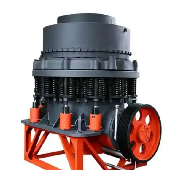
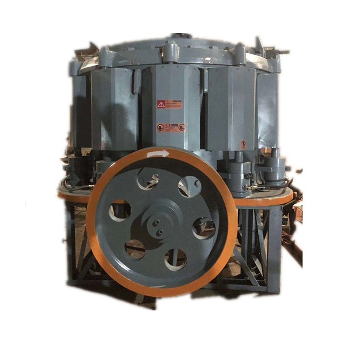
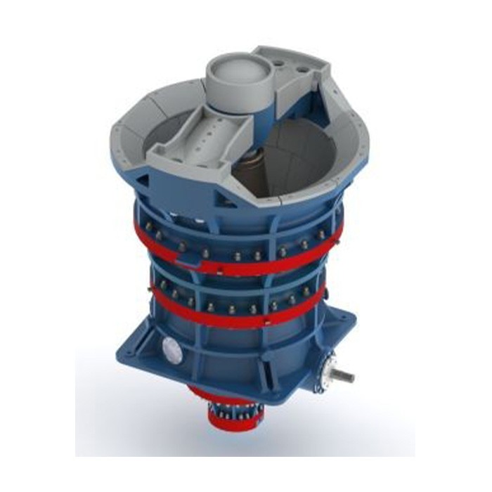
• Vertical Mill
  • video

Vertical Mill

  • SHILONG
  • Shenyang,China
  • 1~2 month
  • 1000 set / year
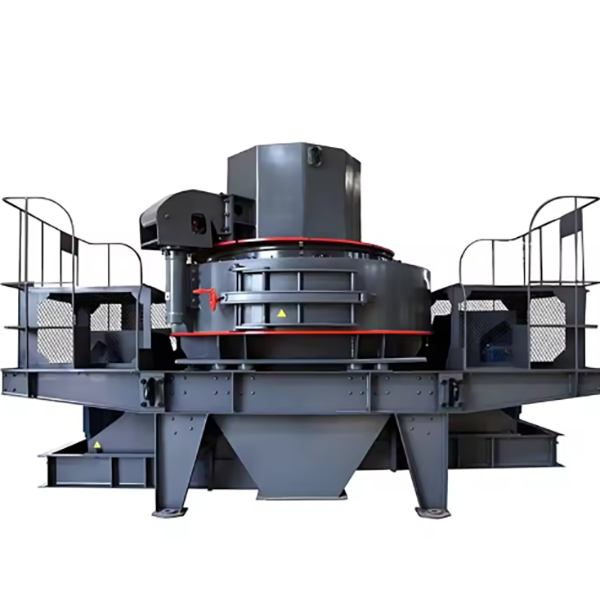
The vertical mill is an efficient grinding equipment integrating crushing, drying, grinding, and classification, widely used in cement, metallurgy, mining, etc. It operates by grinding materials between a rotating grinding disc (ZG35CrMo) and 2–4 grinding rollers (high-chromium cast iron), with hot air drying and carrying powder to a classifier for separation.​ Key components include the main shaft (42CrMo forging), hydraulic system (10–30 MPa), drive system (160–1000 kW motor), and powder collection system (cyclone + bag filter). Manufacturing involves precision casting/forging, heat treatment, and CNC machining, with quality controlled via material testing, NDT, and performance trials (dynamic balancing, load tests).​ Installation requires a stable foundation, precise alignment of components, and system commissioning. It offers 30–50% higher efficiency than ball mills, with adjustable product fineness (80–400 mesh) and low energy consumption
Detailed Introduction to Vertical Mill
1. Overview and Application of Vertical Mill
Vertical mill is a high-efficiency grinding equipment integrating crushing, drying, grinding, and classification. It works on the principle of material being crushed and ground between a rotating grinding disc and grinding rollers. The motor drives the grinding disc to rotate, and materials are fed into the center of the disc, then moved to the edge by centrifugal force. Under the pressure of the grinding rollers, materials are crushed and ground into powder, which is then carried by hot air to the classifier. Fine particles that meet the fineness requirement are collected as products, while coarse particles fall back to the grinding disc for re-grinding.
This equipment is widely used in cement, metallurgy, mining, electric power, and chemical industries, suitable for grinding various materials such as limestone, coal, slag, and ore. It features high grinding efficiency (30–50% higher than ball mills), low energy consumption, and adjustable product fineness (80–400 mesh), making it an ideal choice for large-scale powder production.
2. Composition and Structure of Vertical Mill
Vertical mill consists of several key systems working in coordination to achieve efficient grinding:
2.1 Main Body Structure
  • Grinding Disc: A large cast steel (ZG35CrMo) disc with a diameter of 1.5–5 m, featuring a groove or step structure on the surface to drive materials to the edge. It is mounted on the main shaft and rotated by the motor.

  • Grinding Rollers: 2–4 rollers (depending on the model) made of high-chromium cast iron (Cr20–25) or alloy steel, with a diameter of 0.5–2 m. They are installed above the grinding disc, pressing materials under hydraulic pressure (10–30 MPa) to realize grinding.

  • Main Shaft: A forged alloy steel (42CrMo) shaft connecting the grinding disc and the motor, with a diameter of 200–600 mm. It transmits torque and bears the weight of the grinding disc and materials.

  • Frame: A welded or cast steel structure supporting all components, including the upper frame (housing the classifier) and lower frame (supporting the main shaft and motor).

2.2 Feeding and Drying System
  • Feeding Device: A screw feeder or belt conveyor that feeds materials into the grinding disc at a stable rate. It is equipped with a material level sensor to control the feeding amount.

  • Hot Air System: Includes a hot air furnace or waste gas pipeline, which introduces hot air (150–350°C) into the mill. The hot air dries materials (moisture content ≤15%) and carries powder to the classifier.

2.3 Classification System
  • Classifier: A dynamic rotor classifier installed at the top of the mill, consisting of a rotating impeller and a stationary guide vane. It separates fine and coarse particles by centrifugal force: fine particles pass through the impeller gap, while coarse particles are thrown back. The classifier speed (1000–3000 rpm) is adjustable to control product fineness.

2.4 Hydraulic System
  • Hydraulic Cylinders: 2–4 cylinders that provide pressure to the grinding rollers, adjusting the grinding force according to material hardness. The system is equipped with a pressure relief valve for overload protection.

  • Lifting Device: Hydraulic cylinders for lifting the grinding rollers during maintenance, allowing easy access to the grinding disc.

2.5 Drive System
  • Motor: A high-power asynchronous motor (160–1000 kW) connected to the main shaft via a reducer (planetary or bevel gear reducer) to reduce speed and increase torque. The grinding disc speed is 30–100 rpm.

2.6 Powder Collection System
  • Cyclone Separator: Collects most of the fine powder from the air flow, with a collection efficiency of ≥95%.

  • Bag Filter: Further captures fine dust in the exhaust gas to meet environmental standards (emission concentration ≤30 mg/m³).

3. Manufacturing Processes of Vertical Mill
3.1 Grinding Disc (ZG35CrMo Cast Steel)
  • Pattern Making: A full-scale wooden or metal pattern is made with a shrinkage allowance of 1.2–1.5%, including groove details.

  • Molding: Resin-bonded sand molds are used, with the cavity coated with a zirconium-based refractory coating to improve surface quality.

  • Melting and Pouring: Cast steel is melted in an arc furnace at 1520–1560°C, then poured into the mold at 1480–1520°C. The pouring process is controlled to avoid porosity and cold shut defects.

  • Heat Treatment: Normalization at 880–920°C (air-cooled) followed by tempering at 550–600°C to relieve internal stress and achieve hardness HB 200–240.

3.2 Grinding Rollers (High-Chromium Cast Iron Cr20–25)
  • Casting: Foam patterns are used for sand casting. Molten iron (1450–1500°C) with chromium and molybdenum additives is poured into the mold.

  • Heat Treatment: Solution annealing at 980–1020°C (air-cooled) and tempering at 280–320°C to achieve hardness HRC 60–65 and wear resistance.

3.3 Main Shaft (42CrMo Forging)
  • Forging: Steel billets are heated to 1150–1200°C, then forged into a stepped shaft shape through upsetting and drawing to align grain flow.

  • Heat Treatment: Quenching at 840–860°C (oil-cooled) and tempering at 560–600°C to reach HRC 28–32, with tensile strength ≥900 MPa.

4. Processing Processes
4.1 Grinding Disc Machining
  • Rough Machining: CNC milling shapes the disc surface and grooves, leaving a 2–3 mm allowance. Boring machines process the central hole for the main shaft.

  • Precision Machining: Grinding the disc surface to flatness ≤0.1 mm/m and surface roughness Ra1.6 μm. Groove dimensions are finished to ensure uniform material movement.

4.2 Grinding Roller Machining
  • Turning: CNC lathe processes the outer circle and roller shaft, leaving 0.5–1 mm grinding allowance.

  • Grinding: The roller surface is ground to a cylindrical shape with IT6 tolerance and Ra0.8 μm roughness, ensuring even contact with the grinding disc.

4.3 Main Shaft Machining
  • Turning: CNC lathe processes steps, keyways, and threads, leaving 0.3–0.5 mm grinding allowance.

  • Grinding: Journal surfaces are ground to IT5 tolerance and Ra0.4 μm roughness, ensuring coaxiality ≤0.01 mm for stable rotation.

4.4 Frame Machining
  • Welding and Stress Relief: Welded frames are annealed at 600–650°C to eliminate stress.

  • Milling: CNC milling machines process mounting surfaces for the main shaft, grinding rollers, and classifier, ensuring flatness ≤0.15 mm/m.

5. Quality Control Processes
  • Material Testing:

  • Spectrometric analysis verifies chemical composition (e.g., Cr content in grinding rollers).

  • Tensile and impact tests confirm mechanical properties (e.g., main shaft impact energy ≥60 J/cm²).

  • Dimensional Inspection:

  • CMM checks critical dimensions: grinding disc flatness, roller roundness, and main shaft coaxiality.

  • Laser scanning validates the classifier impeller profile to ensure accurate classification.

  • Non-Destructive Testing (NDT):

  • UT detects internal defects in the grinding disc and main shaft (defects >φ3 mm rejected).

  • MPT inspects grinding rollers and shafts for surface cracks.

  • Performance Testing:

  • Dynamic Balancing: The grinding disc and classifier rotor are balanced to G2.5 grade (vibration ≤2.5 mm/s).

  • Test Run: Empty run for 4 hours to check bearing temperature (≤70°C) and noise (≤85 dB). Load test with limestone for 12 hours to verify output (50–500 t/h), product fineness, and energy consumption.

6. Installation Process
  • Foundation Preparation: Reinforced concrete foundation (C30 grade) with embedded bolts, cured for 28 days. Levelness tolerance is ≤0.1 mm/m.

  • Lower Frame Installation: Hoisted to the foundation, leveled with shims, and anchor bolts tightened to 70% torque.

  • Main Shaft and Grinding Disc Assembly: Main shaft is installed in the lower frame’s bearing seats, grinding disc mounted on the shaft, and aligned to ensure runout ≤0.05 mm.

  • Grinding Rollers Installation: Rollers are lifted into position, hydraulic cylinders connected, and initial pressure (5–10 MPa) applied for alignment.

  • Classifier and Feeding Device Mounting: Classifier is bolted to the upper frame, with impeller clearance adjusted to 1–3 mm. Feeding device is installed and aligned with the grinding disc center.

  • Hydraulic and Electrical System Connection: Pipes are flushed (NAS 8 cleanliness), and wiring is checked for correct phase sequence. The PLC control system is programmed with grinding parameters.

  • Commissioning:

  • Hot air system is tested to ensure temperature and flow stability.

  • Empty run for 2 hours, then gradual feeding to 100% load. Classifier speed is adjusted to achieve target fineness.

  • All systems are monitored for 24 hours to confirm stable operation, with no leaks or abnormal vibrations.

Vertical mill, through advanced manufacturing and strict quality control, delivers efficient and reliable powder grinding, playing a key role in industrial production lines requiring high-performance grinding equipment

Related Products

Get the latest price? We will reply as soon as possible (within 12 hours)