• CH Series Cone Crusher
  • video

CH Series Cone Crusher

  • SHILONG
  • Shenyang,China
  • 1~2 month
  • 1000 set / year
The CH series cone crusher is a high-performance medium-to-fine crushing equipment for hard materials, widely used in mining and aggregate production, with a capacity up to 2000 t/h and product cubicity ≥85%. It operates via lamination crushing, where the motor-driven eccentric shaft sleeve makes the moving cone swing, crushing materials between it and the fixed cone.​ Structurally, it includes a cast steel main frame, a crushing assembly (moving cone with 42CrMo body and Cr20 liner, segmented fixed cone), a transmission system (eccentric shaft sleeve, bevel gears, variable-frequency motor), a hydraulic control system (6–12 cylinders for discharge port adjustment and overload protection), and lubrication/dustproof systems.​ Key components undergo precision manufacturing: frames and eccentric sleeves via casting (ZG270-500/ZG35CrMo) with heat treatment; moving cone via forging (42CrMo) and machining. Quality control involves material testing, dimensional inspection (CMM, laser scanning), NDT (UT, MPT), and performance tests.​ Installation includes foundation preparation, frame mounting, component assembly, system connection, and commissioning. It delivers reliable performance in large-scale operations


CH420 cone crusher


Detailed Introduction to CH Series Cone Crusher
1. Overview and Application of CH Series Cone Crusher
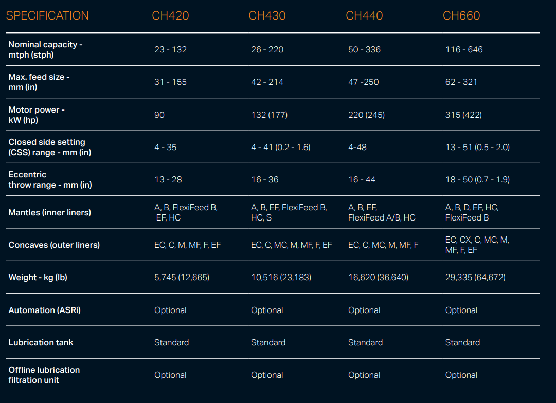
The CH series cone crusher is a high-performance medium-to-fine crushing equipment developed for hard and abrasive materials, widely used in mining, aggregate production, and metallurgical industries. It integrates advanced technologies such as optimized cavity design, hydraulic adjustment, and intelligent control, featuring high crushing efficiency (up to 2000 t/h), excellent product cubicity (≥85%), and strong adaptability to materials like granite, basalt, and ore.
Its working principle is based on lamination crushing: the motor drives the eccentric shaft sleeve to rotate, causing the moving cone to swing periodically. Materials are squeezed, bent, and impacted between the moving cone and fixed cone, gradually crushed into uniform particles and discharged through the adjustable discharge port. The series includes models such as CH430, CH660, and CH890, covering different processing capacities to meet diverse production needs.
2. Composition and Structure of CH Series Cone Crusher
The CH series cone crusher consists of core assemblies with precise coordination, ensuring stable and efficient operation:
2.1 Main Frame Assembly
  • Upper Frame: A cast steel (ZG270-500) cylindrical structure with a flange at the top for connecting the feed hopper. Its inner wall is machined to match the fixed cone liner, and radial reinforcing ribs (thickness 40–100 mm) enhance rigidity against crushing forces.

  • Lower Frame: A heavy-duty cast steel (ZG35CrMo) base housing the eccentric shaft sleeve, main shaft bearing, and hydraulic cylinders. It is bolted to the foundation with anchor bolts (M30–M60) and features internal oil passages for lubrication.

2.2 Crushing Assembly
  • Moving Cone: Comprises a forged 42CrMo cone body and a high-chromium cast iron (Cr20) liner. The cone body has a spherical bottom fitting the main shaft’s spherical bearing, enabling flexible swing. The liner is fixed via zinc alloy casting to ensure tight contact, with a wear-resistant layer thickness of 30–80 mm.

  • Fixed Cone (Concave): A segmented annular liner (3–6 segments) made of Cr20 or ZGMn13, mounted on the upper frame. Each segment’s cavity profile (angle 18°–25°) is optimized for specific particle size requirements, with interlocking structures to prevent material leakage.

2.3 Transmission and Drive System
  • Eccentric Shaft Sleeve: A cast steel (ZG35CrMo) sleeve with an eccentricity of 10–30 mm, driving the main shaft’s oscillation. It is equipped with a large bevel gear (20CrMnTi, carburized and quenched) and mounted on spherical roller bearings.

  • Bevel Gear Pair: The small bevel gear (mounted on the input shaft) and large bevel gear transmit power from the motor, with a transmission ratio of 1:4–1:6.

  • Motor and V-Belt Drive: A variable-frequency motor (160–630 kW) connected to the input shaft via V-belts, with a pulley speed of 980–1480 rpm.

2.4 Hydraulic and Control System
  • Hydraulic Adjustment Unit: 6–12 hydraulic cylinders (working pressure 16–25 MPa) around the lower frame adjust the discharge port (5–50 mm) by lifting/lowering the fixed cone. Position sensors ensure precision (±0.1 mm).

  • Safety System: Overload protection via pressure relief valves. When uncrushable materials enter, cylinders retract to expand the discharge port, expel foreign matter, and reset automatically.

  • Intelligent Control Cabinet: PLC-based system monitoring temperature, pressure, and power, with remote operation and fault diagnosis functions.

2.5 Lubrication and Dustproof System
  • Thin Oil Lubrication: An independent system with dual pumps, coolers, and filters, circulating ISO VG 46 oil to bearings and gears at 0.2–0.4 MPa, maintaining temperature <55°C.

  • Dustproof Structure: Labyrinth seals + oil seals + air purge (0.3–0.5 MPa) prevent dust ingress, with a water spray option for high-dust environments.

3. Casting Processes for Key Components
3.1 Frame (ZG270-500/ZG35CrMo)
  • Pattern Making: Full-scale 3D-printed resin patterns with shrinkage allowances (1.2–1.5%), including rib details and oil passages.

  • Molding: Resin-bonded sand molds with zirconium coating (0.2–0.3 mm thick) for surface finish. Cores form internal cavities.

  • Melting and Pouring:

  • ZG270-500: Melted in an induction furnace at 1520–1560°C, poured at 1480–1520°C under vacuum 辅助 to reduce porosity.

  • ZG35CrMo: Alloyed with Cr (0.8–1.2%) and Mo (0.2–0.3%), poured at 1500–1540°C.

  • Heat Treatment: Normalization (880–920°C, air-cooled) + tempering (550–600°C) to achieve HB 180–220, relieving internal stress.

3.2 Eccentric Shaft Sleeve (ZG35CrMo)
  • Molding: Shell molding with 酚醛树脂 binder for precision (±0.1 mm on eccentric bore).

  • Pouring and Heat Treatment: Poured at 1500–1540°C, then quenched (850°C, oil-cooled) + tempered (580°C) to attain HB 220–260 and tensile strength ≥785 MPa.

3.3 Moving Cone Body (42CrMo Forging)
  • Forging: Billet heated to 1150–1200°C, upset and forged into conical shape with spherical base, ensuring grain flow alignment.

  • Heat Treatment: Quenched (840°C, water-cooled) + tempered (560°C) to reach HRC 28–32, tensile strength ≥900 MPa.

4. Machining Processes
4.1 Frame Machining
  • Rough Machining: CNC milling to shape flanges and ribs, leaving 2–3 mm allowance. Boring machines create bearing seats (IT7 tolerance).

  • Precision Machining: Grinding flange surfaces to Ra1.6 μm, flatness ≤0.1 mm/m. Drilling/tapping bolt holes (M30–M60, 6H class) with positional accuracy ±0.1 mm.

4.2 Eccentric Shaft Sleeve Machining
  • Turning: CNC lathe machines outer diameter and eccentric bore (IT8), leaving 0.5 mm grinding allowance.

  • Grinding: Outer diameter and bore ground to IT6, Ra0.8 μm. Gear mounting face perpendicularity ≤0.02 mm/100 mm.

4.3 Moving Cone Machining
  • Milling: CNC machining centers shape cone surface (tolerance ±0.05°) and spherical base (Ra3.2 μm).

  • Liner Mounting Surface: Machined to flatness ≤0.1 mm/m for zinc alloy bonding.

5. Quality Control Processes
  • Material Testing:

  • Spectrometric analysis verifies chemical composition (e.g., ZG35CrMo: C 0.32–0.40%).

  • Tensile/impact tests confirm mechanical properties (42CrMo: impact energy ≥60 J/cm²).

  • Dimensional Inspection:

  • CMM checks critical dimensions (eccentricity, cone angle) with tolerance ±0.05 mm.

  • Laser scanning validates cavity profile matching design.

  • NDT:

  • UT detects internal defects in castings (defects >φ3 mm rejected).

  • MPT inspects forgings for surface cracks (>1 mm rejected).

  • Performance Testing:

  • Dynamic balancing (G2.5 grade) for rotor assemblies.

  • 48-hour load test with granite: capacity, particle size, and liner wear monitored.

6. Installation Process
  • Foundation Preparation: Concrete foundation (C30 grade) with embedded anchor bolts, levelness ≤0.1 mm/m, cured for 28 days.

  • Lower Frame Installation: Hoisted to foundation, leveled with shims, anchor bolts pre-tightened (30% torque).

  • Eccentric Sleeve and Main Shaft Assembly: Eccentric sleeve installed in lower frame, main shaft inserted into sleeve, bearings lubricated.

  • Moving Cone Installation: Hoisted and mated with main shaft, zinc alloy poured between cone body and liner (temperature 450–500°C).

  • Upper Frame and Fixed Cone Mounting: Upper frame bolted to lower frame, fixed cone segments installed with gaskets, tightened sequentially.

  • Hydraulic and Lubrication System Connection: Pipes flushed (oil cleanliness NAS 8), hoses connected, pressure tested (1.5× working pressure).

  • Commissioning: Empty run (2 hours) to check rotation and noise, then load test (8 hours) with material, adjusting discharge port to design size.

The CH series cone crusher, through precise manufacturing and strict quality control, delivers reliable performance in large-scale crushing operations, ensuring high efficiency and product quality


Related Products

Get the latest price? We will reply as soon as possible (within 12 hours)