Detailed Introduction to Old Spring Cone Crusher
1. Overview and Function of Old Spring Cone Crusher
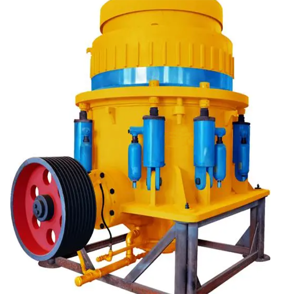
The old spring cone crusher is a classic type of cone crusher widely used in mining, metallurgy, construction, and road - building industries for secondary and tertiary crushing of various ores and rocks. It has a long - standing reputation for its reliable performance in reducing the size of hard and medium - hard materials such as granite, basalt, limestone, and iron ore.
Its working principle is based on the compression and impact of materials between a moving cone (mantle) and a stationary cone (concave). The motor drives the eccentric shaft sleeve, which in turn makes the mantle gyrate eccentrically. As the mantle moves, the gap between it and the concave continuously changes, squeezing and crushing the materials fed into the crushing chamber until they reach the desired particle size and are discharged from the bottom of the crusher.
2. Composition and Structure of Old Spring Cone Crusher
The old spring cone crusher is composed of several key components, each playing a crucial role in the crushing process:
2.1 Frame
The frame is the main structural component, typically made of high - strength cast steel (such as ZG270 - 500). It provides a stable base and support for all other components. The upper part of the frame houses the concave, while the lower part supports the eccentric shaft sleeve, main shaft, and other moving parts. Reinforcing ribs are often added to the frame to enhance its rigidity and withstand the high - impact forces generated during crushing. The frame is designed to be robust, with a thickness of 30 - 50 mm in critical areas.
2.2 Moving Cone (Mantle)
The mantle is a conical - shaped component made of high - manganese steel (such as ZGMn13) or high - chromium cast iron. It is mounted on the main shaft and gyrates eccentrically within the concave. The surface of the mantle is designed with a specific profile to effectively crush the materials. The mantle's thickness ranges from 30 - 80 mm, depending on the model and application. The bottom of the mantle is connected to the main shaft through a spherical bearing, allowing for smooth and stable gyratory motion.
2.3 Stationary Cone (Concave)
The concave is the stationary outer part of the crushing chamber. It is also made of wear - resistant materials like high - manganese steel or high - chromium cast iron. The concave is fixed to the upper part of the frame and has a conical shape that matches the mantle. The inner surface of the concave is lined with replaceable wear - liners. The concave's structure is designed to withstand the impact and abrasion of the crushed materials, with a thickness of 25 - 60 mm.
2.4 Eccentric Shaft Sleeve
The eccentric shaft sleeve is a key component for transmitting motion. It is made of alloy cast steel (such as ZG35CrMo). The eccentric shaft sleeve rotates around the main shaft, causing the mantle to gyrate eccentrically. It is equipped with a large - diameter bevel gear that meshes with a small bevel gear on the transmission shaft. The eccentricity of the shaft sleeve is carefully designed to control the amplitude of the mantle's gyratory motion, usually ranging from 10 - 30 mm.
2.5 Transmission System
The transmission system consists of a motor, V - belts, a pulley, a transmission shaft, and bevel gears. The motor (usually with a power range of 55 - 315 kW) provides the driving force. The V - belts transfer the power from the motor to the pulley on the transmission shaft. The transmission shaft then rotates the small bevel gear, which meshes with the large bevel gear on the eccentric shaft sleeve, driving the rotation of the eccentric shaft sleeve. The transmission ratio of the bevel gears is typically in the range of 1:4 - 1:6.
2.6 Spring Assembly
Springs are an important safety and adjustment feature in the old spring cone crusher. A set of high - strength springs (usually made of alloy spring steel, such as 60Si2Mn) is installed around the lower part of the frame. In case of the presence of uncrushable materials (such as tramp iron) in the crushing chamber, the springs compress, allowing the mantle to move downward and increase the discharge gap, preventing damage to the crusher. The spring force can be adjusted to control the crushing force and the discharge size. The spring compression range is usually 20 - 50 mm.
2.7 Feeding and Discharging System
The feeding system typically includes a feed hopper at the top of the crusher. The feed hopper is designed to evenly distribute the materials into the crushing chamber. The size of the feed hopper varies according to the capacity of the crusher, with a volume range of 0.5 - 3 cubic meters. The discharging system is located at the bottom of the crusher. The discharged materials fall through the adjustable discharge gap, which can be adjusted by changing the position of the concave or using the spring - adjustment mechanism. The discharge gap can be adjusted in the range of 3 - 50 mm to control the particle size of the final product.
3. Manufacturing Processes of Old Spring Cone Crusher
3.1 Frame Manufacturing
Pattern Making: A full - scale pattern is made, usually from wood or 3D - printed resin, with allowances for shrinkage (1.5 - 2.0%) and machining. The pattern is designed to accurately represent the complex shape of the frame, including all the internal cavities and mounting points.
Molding: Resin - bonded sand molds are used for casting the frame. The sand is mixed with resin binders to form a hard - setting mold. Cores are inserted into the mold to create internal cavities, such as those for the eccentric shaft sleeve and main shaft. The mold is then coated with a refractory coating to improve the surface finish of the casting.
Casting: High - strength cast steel (ZG270 - 500) is melted in an induction furnace at a temperature of 1520 - 1560 °C. The molten metal is carefully poured into the mold at a controlled rate to ensure proper filling and minimize the formation of defects. After casting, the frame is allowed to cool slowly in the mold to reduce internal stress.
Heat Treatment: The cast frame is subjected to a heat - treatment process. First, it is normalized at a temperature of 880 - 920 °C and then air - cooled. This is followed by tempering at 550 - 600 °C to improve the mechanical properties, such as hardness (HB 180 - 220) and toughness.
Machining: The heat - treated frame is then machined. CNC milling machines are used to machine the mounting surfaces for the concave, eccentric shaft sleeve, and other components. The machining accuracy is controlled within ±0.1 mm for key dimensions. Drilling and tapping operations are performed to create holes for bolts and other fasteners.
3.2 Moving Cone (Mantle) Manufacturing
Forging: High - manganese steel (ZGMn13) or high - chromium cast iron billets are heated to 1100 - 1150 °C and then forged into the conical shape of the mantle. Forging helps to align the grain structure of the material, improving its strength and wear resistance. Multiple forging steps may be involved to achieve the desired shape and dimensional accuracy.
Heat Treatment: After forging, the mantle is heat - treated. For high - manganese steel, it is solution - annealed at 1050 - 1100 °C and then water - quenched to obtain a high - hardness martensitic structure. The hardness of the mantle after heat treatment is typically HRC 45 - 55.
Machining: The heat - treated mantle is machined to achieve the final dimensions. CNC lathes and milling machines are used to machine the outer conical surface, the bottom surface for the spherical bearing, and any other necessary features. The surface finish of the working surface of the mantle is carefully controlled to ensure smooth crushing action, with a roughness of Ra 3.2 - 6.3 μm.
3.3 Stationary Cone (Concave) Manufacturing
Casting: Similar to the frame, the concave is cast using resin - bonded sand molds. High - manganese steel or high - chromium cast iron is melted in an induction furnace at 1450 - 1500 °C and poured into the mold. The casting process is carefully controlled to ensure uniform thickness and minimize porosity.
Heat Treatment: The cast concave is heat - treated to improve its mechanical properties. It is usually normalized and tempered. For high - manganese steel, the normalization temperature is around 950 - 1000 °C, followed by tempering at 200 - 300 °C to achieve the desired hardness and toughness.
Machining: After heat treatment, the concave is machined. The inner surface is machined to a specific profile to match the mantle, and the outer surface is machined for mounting on the frame. The machining accuracy for the inner surface profile is within ±0.5 mm, and the surface roughness is Ra 6.3 - 12.5 μm.
3.4 Eccentric Shaft Sleeve Manufacturing
Machining: CNC lathes and grinding machines are used to machine the outer and inner diameters of the eccentric shaft sleeve, as well as the surfaces for the bevel gear and bearings. The machining accuracy for the eccentric diameter is within ±0.05 mm, and the surface roughness of the bearing - contacting surfaces is Ra 0.8 - 1.6 μm.
3.5 Spring Manufacturing
4. Processing and Finishing Processes
Painting: All exposed metal surfaces of the crusher, such as the frame, are painted with anti - corrosion paint. The paint is usually applied in multiple coats. First, a primer coat is applied to improve adhesion, followed by one or more top - coats. The paint used is typically a high - quality epoxy - based paint, which provides good protection against rust and corrosion in harsh working environments.
Lubrication: All moving parts, such as bearings, shafts, and gears, are lubricated with appropriate lubricants. For bearings, grease (such as lithium - based grease) is often used, while for gears, oil - based lubricants are applied. The lubrication points are designed to be easily accessible for regular maintenance.
The crusher is assembled in a specific sequence. First, the frame is placed on a stable workbench. Then, the eccentric shaft sleeve is installed in the frame, followed by the main shaft and the mantle. The concave is then mounted on the upper part of the frame. The spring assembly is installed around the lower part of the frame, and the transmission system is assembled and connected.
During assembly, all components are carefully aligned and fastened using bolts and nuts. Torque wrenches are used to ensure that the bolts are tightened to the specified torque values, typically in the range of 100 - 500 N·m, depending on the size and type of the bolt.
After assembly, the crusher is adjusted. The discharge gap between the mantle and the concave is adjusted using the spring - adjustment mechanism or other adjustment devices. The adjustment is done to achieve the desired particle size of the crushed product. The adjustment accuracy for the discharge gap is within ±1 mm.
5. Quality Control Processes
Chemical Composition Analysis: Samples of the raw materials used for casting and forging, such as cast steel, high - manganese steel, and alloy steel, are analyzed using spectrometers to verify their chemical composition. For example, the carbon content in ZGMn13 should be in the range of 1.0 - 1.4%, and the manganese content should be 11 - 14%.
Mechanical Property Testing: Tensile tests, impact tests, and hardness tests are performed on samples of the materials. For high - strength cast steel (ZG270 - 500), the tensile strength should be at least 500 MPa, and the elongation should be not less than 18%.
Coordinate Measuring Machine (CMM) Inspection: A CMM is used to measure the key dimensions of all components, such as the diameter of the eccentric shaft sleeve, the height and diameter of the mantle and concave, and the distance between mounting holes on the frame. The measurement accuracy of the CMM is within ±0.02 mm.
Gauge Inspection: Special - purpose gauges are used to check the size of features such as the thread pitch of bolts and the fit between mating parts. For example, the fit between the main shaft and the bearing is checked using a bore gauge and a shaft gauge to ensure that the clearance is within the specified range.
Ultrasonic Testing (UT): UT is used to detect internal defects in castings, such as porosity, cracks, and inclusions. The ultrasonic waves are transmitted through the material, and any defects are detected by analyzing the reflected waves. Defects larger than a certain size (usually 3 - 5 mm) are considered unacceptable.
Magnetic Particle Testing (MPT): MPT is used to detect surface and near - surface cracks in ferromagnetic materials, such as steel components. A magnetic field is applied to the component, and magnetic particles are sprinkled on the surface. Cracks will attract the magnetic particles, making them visible.
Empty - Load Test: The assembled crusher is run without any material for a period of 2 - 4 hours. During this test, the rotation of the shaft, the operation of the transmission system, and the stability of the machine are checked. The vibration level of the machine is measured using vibration sensors, and it should be within the specified limit (usually less than 10 mm/s).
Load Test: The crusher is then subjected to a load test. A representative sample of the material to be crushed (such as granite or limestone) is fed into the crusher at a controlled rate. The production capacity, the particle - size distribution of the crushed product, and the wear rate of the mantle and concave are measured. The production capacity should meet the rated value of the crusher, and the particle - size distribution should be within the specified range.
6. Installation Process
A concrete foundation is poured for the crusher. The foundation is designed according to the weight and size of the crusher, as well as the dynamic forces generated during operation. The concrete used is typically of a high - strength grade, such as C30 - C40.
The crusher is carefully lifted and placed on the foundation using a crane or other lifting equipment. The crusher is aligned with the anchor bolts, and shims are placed under the frame to adjust the level and alignment of the crusher. The shims are made of steel and have a thickness range of 0.5 - 5 mm.
The anchor bolts are then tightened using a torque wrench to the specified torque value, usually in the range of 300 - 800 N·m, depending on the size of the bolt. The tightening process is done in a cross - pattern to ensure even distribution of the load.
The lubrication system, which includes oil pumps, filters, and oil lines, is installed. The oil lines are connected to all the lubrication points on the crusher, such as bearings and gears. The lubrication system is filled with the appropriate lubricant, and the oil level is checked