Hammer crusher is one of the main equipment for fine crushing of limestone, coal or other brittle materials with a hardness below medium in the metallurgical, building materials, chemical and hydropower industries. It has the characteristics of large crushing ratio, high production capacity and uniform product particle size. One-stage hammer crusher can crush materials with a feed particle size of 1100mm to less than 20mm at one time, so the traditional two-stage or three-stage crushing can be changed to one-stage crushing, simplifying the process flow, saving equipment investment, reducing consumption and other production costs.
Our company has a history of designing and manufacturing hammer crushers for more than 30 years. The product structure is advanced, the performance is reliable, the operation is stable, and the energy consumption is low. The hammer crushers produced by our company have formed a series and are well received by users at home and abroad.
In 1980, our company produced a Φ2000×2000 one-stage hammer crusher for Guangxi Litang Cement Plant. After several years of operation, it has also been well received by users.
Hammer crushers can be divided into reversible and irreversible types. The rotor of the reversible hammer crusher can be reversed and is generally used for fine crushing; the rotor of the irreversible hammer crusher cannot be reversed and is generally used for medium crushing. The first-stage hammer crusher is irreversible.
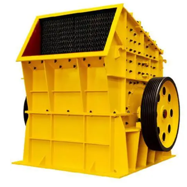
Ordinary hammer crushers are mainly composed of a frame, a rotor, screen bars, a striking plate and an adjustment device. The motor drives the rotor to rotate at high speed through a coupling. The ore entering the crusher is crushed by the impact of the hammer on the rotor. The crushed ore obtains kinetic energy from the outside of the hammer and rushes to the striking plate and screen bars in the frame at high speed; at the same time, the ores collide with each other, thus suffering multiple crushing. Ore smaller than the screen bar grid holes is discharged from the grid holes; individual larger ore blocks are crushed again on the grid plate by the combined effects of the impact, extrusion and grinding of the hammer head, and the ore is squeezed out of the grid holes by the hammer head, thereby obtaining the product of the required particle size.
The first-stage hammer crusher is mainly composed of a frame, a rotor, a feed roller, a grate bar, a hydraulic opening device, a foundation and other parts. The main motor directly drives the rotor with a flywheel through a coupling. The ore is fed into the crusher feed port by a heavy plate feeder. The feeding is required to be carried out over the full width of the feeder to achieve uniform feeding. After entering the crusher, large pieces of ore first fall on two rubber-supported shockproof feed rollers. The two feed rollers rotate at different speeds to prevent the ore from wedging between the two rollers. The latter rotates faster than the former. A part of the fine material in the feed falls directly between the two rollers, and the rest of the ore continues to be fed into the crushing area. The ore entering the crushing area is crushed or thrown up by the hammer on the high-speed rotating rotor. The ore thrown up at high speed collides with the impact plate in the counter-attack cavity of the frame or the ore blocks collide with each other and are crushed. Then they are brought into the crushing plate and grate section by the hammer, and continue to be crushed until the required particle size is reached and discharged from the gap between the grate bars. The discharged material is transported away by the discharge belt conveyor. In order to prevent foreign objects such as ironware from damaging the machine, the crusher is equipped with a safety door, and its opening and opening force are controlled by a heavy hammer. To meet the different requirements of tube mill and vertical mill, one-stage hammer crusher has two different grates for users to choose. The hydraulic opening frame device is convenient for maintenance and shortens the maintenance parking time.
Detailed Introduction to Hammer Crusher
1. Function and Application of Hammer Crusher
Hammer crusher is a widely used crushing equipment that crushes materials through the high-speed impact of hammers. Its working principle is: the motor drives the rotor to rotate at high speed (800–1500 rpm), and the hammers installed on the rotor hit the materials entering the crushing chamber, breaking them through impact, collision, and shearing. After being crushed to the required particle size, the materials are discharged through the sieve plate at the bottom of the crushing chamber.
It is suitable for crushing medium-hard and brittle materials with compressive strength ≤150 MPa, such as limestone, coal, gypsum, brick, tile, and concrete blocks. It is widely used in industries such as mining, building materials, metallurgy, chemical engineering, and environmental protection due to its simple structure, high crushing efficiency, and low energy consumption.
2. Composition and Structure of Hammer Crusher
Hammer crusher is mainly composed of the following components:
Frame: It is the supporting structure of the entire equipment, divided into upper and lower parts, connected by bolts. The frame is usually made of cast steel (ZG270-500) or thick steel plates (Q355B) welded, with a thickness of 10–30 mm. Its inner wall is lined with wear-resistant liners to prevent wear from materials.
Rotor: The core component that provides power for crushing, consisting of a main shaft, a rotor disk, and hammers.
Rotor disk: A circular plate installed on the main shaft, usually made of cast steel (ZG310-570) or forged steel, with a thickness of 20–50 mm. Several evenly distributed holes are opened on the disk for installing hammer shafts.
Hammers: The key working parts, made of high-chromium cast iron (Cr15–20) or alloy steel (40CrNiMo), with a weight of 1–10 kg. They are hinged on the hammer shafts through hammer eyes and can swing freely to hit materials. The shape of the hammer is usually rectangular, with a sharpened working end to improve crushing efficiency.
Sieve plate: Installed at the bottom of the crushing chamber, it is a grid-like structure made of high manganese steel (ZGMn13) or wear-resistant cast iron. The sieve hole size determines the discharge particle size, generally 5–50 mm. The sieve plate can be replaced according to the required particle size.
Hammer shaft: Used to connect the rotor disk and the hammer, made of 40Cr steel, with high hardness and wear resistance. Its diameter is slightly larger than the hammer eye to ensure the hammer can swing flexibly.
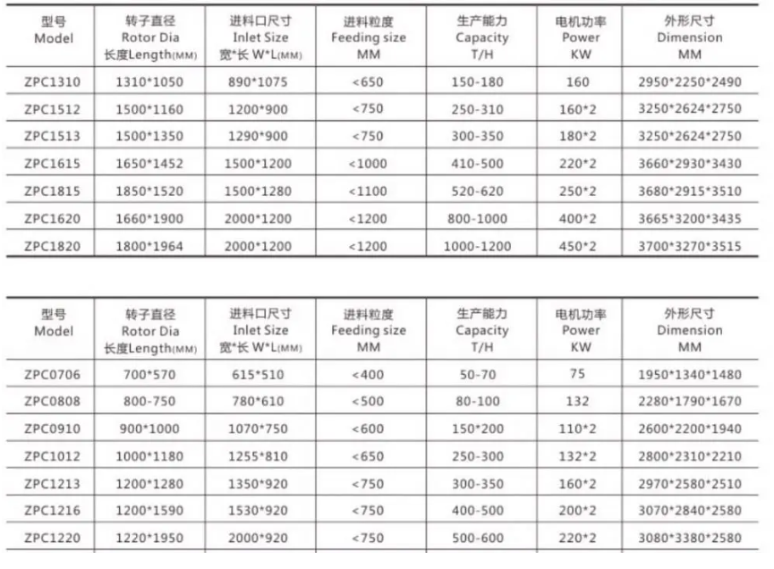
Motor: Provides power for the equipment, connected to the main shaft through a V-belt or coupling. The power of the motor ranges from 5.5–315 kW, depending on the model and processing capacity of the crusher.
3. Casting Processes for Key Components
3.1 Hammers (High-Chromium Cast Iron Cr15–20)
Material preparation: The raw materials are proportioned according to the chemical composition requirements (C 2.8–3.5%, Cr 15–20%, Si 0.5–1.2%, Mn 0.5–1.0%).
Heat treatment: After casting, the hammer is heated to 950–1000 °C for solution annealing, then air-cooled. Then it is tempered at 250–300 °C for 4–6 hours to improve hardness and toughness, making the surface hardness reach HRC 55–65.
3.2 Rotor Disk (Cast Steel ZG310-570)
4. Machining Processes
4.1 Main Shaft (40Cr Alloy Steel)
4.2 Sieve Plate (High Manganese Steel ZGMn13)
4.3 Frame (Welded Structure)
5. Quality Control Processes
Use a vernier caliper, micrometer, and coordinate measuring machine (CMM) to inspect the dimensions of components such as the main shaft, rotor disk, and sieve plate, ensuring they meet the drawing tolerances.
Perform a load test with standard materials, checking the crushing efficiency, discharge particle size, and power consumption. The discharge particle size should meet the design requirements, and the power consumption should be within the specified range.
Through the above manufacturing and quality control processes, the hammer crusher can achieve efficient and stable crushing operations, meeting the needs of various industrial fields