Detailed Introduction to Impact Crusher
1. Overview and Application of Impact Crusher
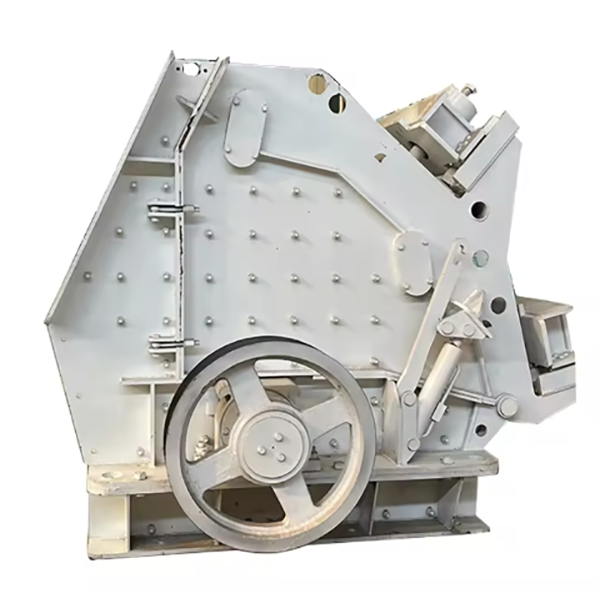
Impact crusher is a high-efficiency crushing equipment that crushes materials through high-speed impact and rebound. Its working principle is: the motor drives the rotor to rotate at high speed (1000–2000 rpm), and the impact hammers installed on the rotor hit the materials entering the crushing chamber. The materials are crushed by impact, then rebound to the impact plate for secondary crushing, and finally discharged through the gap between the impact plate and the rotor when reaching the required particle size.
It is suitable for crushing medium-hard and brittle materials with compressive strength ≤300 MPa, such as limestone, concrete, asphalt, coal, and ore. Due to its advantages of simple structure, high crushing ratio (up to 50:1), and good product particle shape, it is widely used in construction, mining, road construction, and recycling industries.
2. Composition and Structure of Impact Crusher
Impact crusher is mainly composed of the following core components, which work together to complete the crushing process:
2.1 Frame Assembly
Upper Frame: A welded structure made of Q355B steel plates (thickness 10–20 mm), forming the feeding and crushing chamber. It is equipped with a feeding hopper and impact plate adjustment devices, with reinforcing ribs (thickness 8–15 mm) to resist impact forces.
2.2 Rotor Assembly
Impact Hammers: Key working parts made of high-chromium cast iron (Cr15–20) or alloy steel (40CrNiMo). They are hinged on the hammer shafts and can swing freely, with a weight of 2–20 kg depending on the model. The hammer head is designed with a sharp or blunt shape according to material characteristics.
2.3 Impact Plate Assembly
Impact Plates: Wear-resistant plates made of high manganese steel (ZGMn13) or high-chromium cast iron, with a thickness of 20–40 mm. They are installed on the upper frame and form a crushing cavity with the rotor. The number of impact plates is 1–3, depending on the crushing stage (primary or secondary).
2.4 Drive System
2.5 Safety and Auxiliary Devices
3. Casting Processes for Key Components
3.1 Impact Hammers (High-Chromium Cast Iron Cr15–20)
3.2 Rotor Disk (ZG310-570 Cast Steel)
3.3 Main Shaft (40Cr Forging)
4. Machining Processes
4.1 Rotor Disk Machining
Rough Machining: CNC lathe or milling machine processes the outer circle, end face, and hammer shaft holes, leaving a 1–2 mm machining allowance.
4.2 Main Shaft Machining
Turning: CNC lathe processes the outer circle, steps, and keyways, leaving a 0.3–0.5 mm grinding allowance.
4.3 Impact Plates Machining
4.4 Frame Machining
5. Quality Control Processes
Load Test: Crushing standard materials (e.g., limestone) for 8 hours to verify production capacity, discharge particle size, and hammer wear.
6. Installation Process
Through strict manufacturing processes, quality control, and standardized installation, impact crushers can achieve efficient and stable operation, meeting the crushing needs of various industries for medium-hard and brittle materials