Detailed Introduction to CS Series Cone Crusher
1. Overview and Application of CS Series Cone Crusher
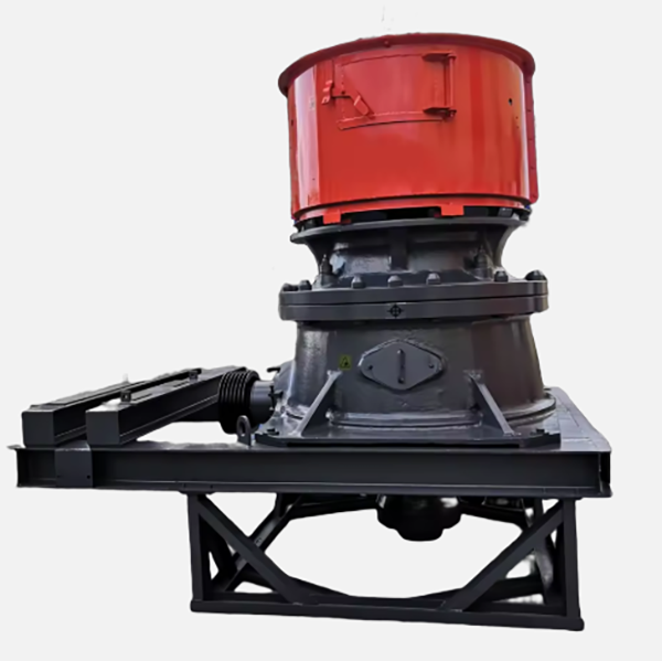
The CS series cone crusher, a paragon of high - performance spring cone crushers, is engineered based on the principles of laminated crushing and the concept of "more crushing and less grinding". This design approach amalgamates high swing frequencies, optimized cavity geometries, and rational stroke lengths, endowing it with a unique set of advantages.
This crusher finds extensive applications across a wide spectrum of industries. In gravel yards, it efficiently processes various stones to produce well - graded aggregates. In mining operations, whether it's extracting iron ore, copper ore, or other valuable minerals, the CS series cone crusher plays a pivotal role in reducing the ore size. In coal mining, it helps in crushing coal to the desired particle size for transportation and further processing. Concrete mixing stations rely on it to break down raw materials into the right - sized components for concrete production. Dry powder mortar plants also benefit from its precise crushing capabilities. Additionally, in power plant desulfurization processes and quartz sand production, the CS series cone crusher proves to be an invaluable asset.
It can handle a diverse range of materials with remarkable efficiency. Pebbles, granite, basalt, iron ore, limestone, quartz, diabase, gold ore, and copper ore are among the many materials that can be effectively crushed. Its versatility in material processing makes it a popular choice in numerous industrial settings.
2. Composition and Structure of CS Series Cone Crusher
The CS series cone crusher is a complex yet highly coordinated mechanical system, composed of several key components:
2.1 Main Frame Assembly
Upper Frame: Constructed from high - strength cast steel (such as ZG270 - 500), the upper frame is designed with a cylindrical shape. It features a flange at the top, which serves as a connection point for the feed hopper. The inner wall of the upper frame is meticulously machined to precisely fit the fixed cone liner. To enhance its structural integrity and withstand the substantial crushing forces, radial reinforcing ribs are incorporated. These ribs, typically with a thickness ranging from 40 - 100 mm, are strategically placed to distribute the load evenly, ensuring the long - term durability of the frame.
Lower Frame: The lower frame, fabricated from heavy - duty cast steel (like ZG35CrMo), is the foundation of the crusher. It houses crucial components such as the eccentric shaft sleeve, main shaft bearing, and in some models, hydraulic cylinders. This frame is securely fastened to the foundation using anchor bolts (commonly in the range of M30 - M60). The lower frame also contains internal oil passages, which are essential for the proper lubrication of moving parts, reducing friction and ensuring smooth operation.
2.2 Crushing Assembly
Moving Cone: The moving cone is a critical part of the crushing mechanism. It consists of a forged 42CrMo cone body and a wear - resistant liner. The cone body is forged with precision, with its spherical bottom designed to fit snugly with the spherical bearing of the main shaft. This allows for a smooth and flexible swinging motion during operation. The wear - resistant liner, made from high - chromium cast iron (Cr20) or manganese steel (ZGMn13), is attached to the cone body using zinc alloy casting. This method ensures a tight and secure bond, with the wear - resistant layer typically having a thickness of 30 - 80 mm to withstand the abrasive forces of the crushing process.
Fixed Cone (Concave): The fixed cone, also known as the concave, is an annular liner mounted on the inner wall of the upper frame. It is usually segmented into 3 - 6 segments, which simplifies installation and replacement. The material of the fixed cone is the same as that of the moving cone liner, providing high wear resistance. Each segment has a carefully designed cavity profile, with an angle typically ranging from 18° - 25°. The interlocking structures between the segments prevent material leakage, ensuring efficient and consistent crushing.
2.3 Transmission and Drive System
Eccentric Shaft Sleeve: Made of cast steel (ZG35CrMo), the eccentric shaft sleeve is a key component in driving the main shaft's oscillation. It has an eccentricity that typically ranges from 10 - 30 mm, which determines the amplitude of the moving cone's swing. The outer surface of the eccentric shaft sleeve is equipped with a large bevel gear, which is made of 20CrMnTi alloy steel and undergoes carburizing and quenching treatment. This treatment enhances the gear's wear resistance and fatigue strength, ensuring reliable power transmission.
Bevel Gear Pair: Comprising a small bevel gear mounted on the input shaft and a large bevel gear fixed on the eccentric shaft sleeve, the bevel gear pair is responsible for transmitting power from the motor. The gear ratio is carefully selected, usually in the range of 1:4 - 1:6, to achieve the desired rotational speed and torque for the eccentric shaft sleeve.
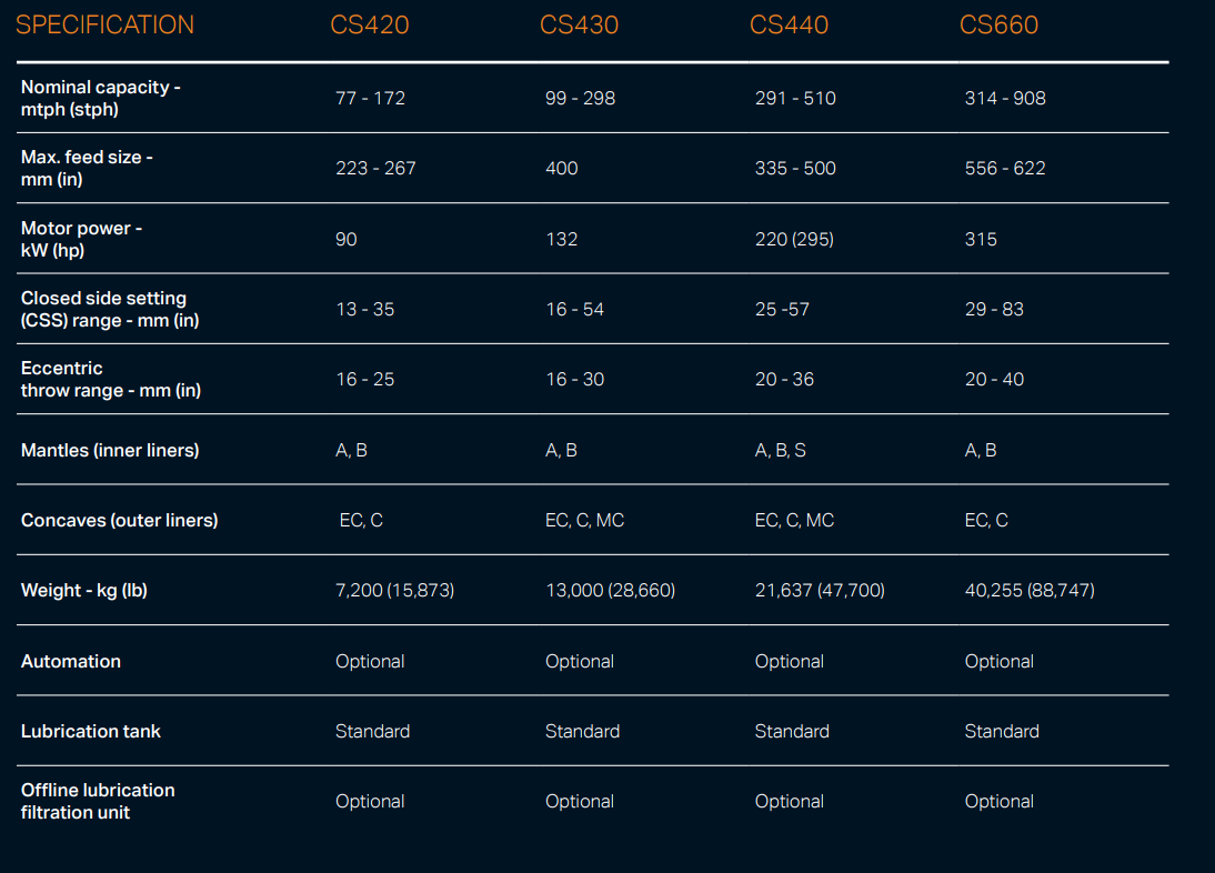
Motor and V - Belt Drive: A variable - frequency motor, with power ratings typically ranging from 160 - 630 kW, provides the power source for the crusher. The motor is connected to the input shaft via V - belts, and the pulley speed can be adjusted in the range of 980 - 1480 rpm. This variable - speed drive system allows for flexibility in operation, enabling the crusher to adapt to different materials and production requirements.
2.4 Hydraulic and Control System
Hydraulic Adjustment Unit: In some advanced models of the CS series, a hydraulic adjustment unit is incorporated. This unit typically consists of 6 - 12 hydraulic cylinders, which are arranged around the lower frame. These cylinders operate at a working pressure of 16 - 25 MPa and are used to adjust the discharge port size, which can range from 5 - 50 mm. Position sensors are integrated into the system to ensure precise control of the discharge port width, with an accuracy of ±0.1 mm.
Safety System: The crusher is equipped with an overload protection system. In models with hydraulic cylinders, pressure relief valves are used to protect against overloading. When uncrushable materials, such as metal objects, enter the crushing cavity, the hydraulic cylinders retract, expanding the discharge port to allow the foreign matter to be expelled. Once the obstruction is removed, the cylinders automatically reset to their original position. In traditional spring - based models, a set of springs (usually 16 pairs of high - performance alloy steel springs) acts as the overload protection mechanism. When excessive force is applied, the springs compress, allowing the moving parts to move and prevent damage to the crusher.
Intelligent Control Cabinet: Some modern CS series cone crushers are equipped with an intelligent control cabinet. This cabinet is based on a Programmable Logic Controller (PLC) system, which monitors various parameters such as temperature, pressure, and power consumption. It also enables remote operation and provides fault diagnosis functions, allowing operators to quickly identify and address any issues that may arise during operation.
2.5 Lubrication and Dustproof System
Thin Oil Lubrication: An independent thin oil lubrication system is employed to ensure the smooth operation of critical components. This system features dual pumps for redundancy, coolers to regulate the oil temperature, and filters to remove contaminants. The system circulates ISO VG 46 oil to bearings and gears, maintaining an oil pressure in the range of 0.2 - 0.4 MPa and keeping the oil temperature below 55°C.
Dustproof Structure: To prevent dust from entering the crusher and affecting its performance, a comprehensive dustproof structure is implemented. This typically includes a combination of labyrinth seals, oil seals, and an air purge system. The air purge system, which operates at a pressure of 0.3 - 0.5 MPa, creates a positive pressure inside the crusher, preventing dust ingress. In high - dust environments, some models may also be equipped with a water spray option to further suppress dust.
3. Casting Processes for Key Components
3.1 Frame (ZG270 - 500/ZG35CrMo)
Pattern Making: High - precision patterns are created for casting the frame. In modern manufacturing, 3D - printed resin patterns are often used. These patterns are designed with shrinkage allowances, typically in the range of 1.2 - 1.5%, to account for the dimensional changes that occur during the casting process. The patterns also incorporate all the intricate details, such as rib structures and oil passages, with high accuracy.
Molding: Resin - bonded sand molds are commonly used for frame casting. The mold cavity is coated with a zirconium - based refractory coating, which is typically 0.2 - 0.3 mm thick. This coating improves the surface finish of the casting and helps in reducing defects. Cores are used to form the internal cavities, such as the oil passages, ensuring proper alignment and dimensional accuracy.
For ZG270 - 500 cast steel, the raw materials are melted in an induction furnace. The melting temperature is carefully controlled within the range of 1520 - 1560°C. To further improve the quality of the casting, vacuum - assisted pouring may be employed. The molten steel is then poured into the mold at a temperature of 1480 - 1520°C, with strict control of the pouring speed to avoid turbulence and the formation of inclusions.
Heat Treatment: After casting, the frame undergoes a series of heat treatment processes. First, normalization is carried out at a temperature of 880 - 920°C, followed by air - cooling. This process refines the grain structure of the metal. Subsequently, tempering is performed at 550 - 600°C to relieve internal stress and achieve a hardness range of HB 180 - 220, ensuring the frame's structural integrity and durability.
3.2 Eccentric Shaft Sleeve (ZG35CrMo)
Molding: Shell molding, which uses a phenolic resin binder, is a preferred method for casting the eccentric shaft sleeve. This process offers high dimensional accuracy, with tolerances of ±0.1 mm on the eccentric bore. The shell mold provides a smooth surface finish, reducing the need for extensive post - casting machining.
Pouring and Heat Treatment: The molten ZG35CrMo steel is poured into the shell mold at a temperature of 1500 - 1540°C. After casting, the eccentric shaft sleeve is quenched in oil at 850°C to harden the surface. This is followed by tempering at 580°C to achieve the desired combination of hardness (HB 220 - 260) and tensile strength (≥785 MPa), ensuring its ability to withstand the high - stress operating conditions.
3.3 Moving Cone Body (42CrMo Forging)
Forging: The 42CrMo steel billet is first heated to a temperature range of 1150 - 1200°C in a gas furnace. This high temperature makes the steel malleable, allowing for efficient forging. The billet is then subjected to a series of upsetting and forging operations to shape it into the conical form with a spherical base. These forging processes ensure that the metal grain flow is aligned with the stress direction, enhancing the mechanical properties of the moving cone body.
Heat Treatment: After forging, the moving cone body undergoes quenching in water at 840°C, which rapidly cools the metal and hardens it. This is followed by tempering at 560°C to relieve internal stress and achieve a hardness of HRC 28 - 32, along with a tensile strength of ≥900 MPa, providing the necessary strength and toughness for its operation in the crusher.
4. Machining Processes
4.1 Frame Machining
Rough Machining: CNC milling machines are used to initially shape the flanges and ribs of the frame. During this process, a machining allowance of 2 - 3 mm is left on the surfaces to be finished later. Boring machines are then employed to create the bearing seats, with dimensional tolerances held to IT7 to ensure a proper fit for the bearings.
Precision Machining: The flange surfaces are ground to achieve a flatness of ≤0.1 mm/m and a surface roughness of Ra1.6 μm. This smooth surface finish is crucial for proper sealing and mechanical connection. Bolt holes, typically in the range of M30 - M60, are drilled and tapped with a thread tolerance of 6H. Precise positioning of these bolt holes is ensured, with an accuracy of ±0.1 mm, to enable secure fastening of various components.
4.2 Eccentric Shaft Sleeve Machining
Turning: CNC lathes are used to machine the outer diameter and the eccentric bore of the shaft sleeve. During the turning process, an allowance of 0.5 mm is left for subsequent grinding operations. The eccentricity of the bore is carefully monitored using a dial indicator to ensure that it meets the design requirements, with a tolerance of ±0.05 mm.
Grinding: The outer diameter and the eccentric bore are ground to achieve a dimensional tolerance of IT6 and a surface roughness of Ra0.8 μm. The gear - mounting face is also machined to ensure perpendicularity to the axis, with a tolerance of ≤0.02 mm/100 mm. This high - precision machining is essential for the smooth operation of the eccentric shaft sleeve and the proper meshing of the bevel gears.
4.3 Moving Cone Machining
Liner Mounting Surface: The surface where the wear - resistant liner is mounted is machined to a flatness of ≤0.1 mm/m. This flat surface is necessary for the zinc alloy casting process, which attaches the liner to the cone body, ensuring a tight and uniform bond.
5. Quality Control Processes
Spectrometric analysis is carried out on all cast and forged components to verify their chemical composition. For example, for ZG35CrMo, the carbon content should be in the range of 0.32 - 0.40%, and the manganese content should be 0.5 - 0.8%. Any deviation from these specified ranges can affect the mechanical properties of the material.
Tensile and impact tests are conducted on test pieces taken from the same batch of materials. For 42CrMo forging, the yield strength should be ≥785 MPa, and the impact energy should be ≥60 J/cm². These tests ensure that the materials can withstand the high - stress conditions during the crusher's operation.
Coordinate Measuring Machines (CMM) are used to measure key dimensions of the components. This includes measuring the eccentricity of the eccentric shaft sleeve, the taper of the moving cone, and the position of bolt holes. The CMM provides highly accurate measurements, with a tolerance of ±0.05 mm, ensuring that the components fit together correctly during assembly.
Ultrasonic Testing (UT) is used to detect internal defects in castings, such as the frames and eccentric shaft sleeves. Any defects with a diameter greater than 3 mm are considered unacceptable, as they can compromise the structural integrity of the component.
Magnetic Particle Testing (MPT) is carried out on forgings, such as the main shaft and the moving cone body, to inspect for surface and near - surface cracks. Cracks longer than 1 mm are rejected, as they can lead to catastrophic failure during operation.
Dynamic balancing is performed on rotor assemblies, such as the eccentric shaft sleeve and the attached components. The balancing process aims to achieve a G2.5 grade, which ensures that the vibration level during operation is ≤2.5 mm/s. This low - vibration operation reduces wear and tear on the components and improves the overall stability of the crusher.
A 48 - hour load test is conducted using standard materials, such as granite. During this test, parameters such as production capacity, discharge particle size distribution, and liner wear are closely monitored. The production capacity should meet the specified values for the particular model, the discharge particle size should be within the desired range, and the liners should exhibit uniform wear to ensure long - term performance.
6. Installation Process
Lower Frame Installation: The lower frame is hoisted into position on the foundation using appropriate lifting equipment. Shims are used to level the frame, and the anchor bolts are initially tightened to 30% of their final torque. This initial tightening allows for minor adjustments during subsequent installation steps.
Moving Cone Installation: The moving cone is hoisted and precisely mated with the main shaft. During the installation of the wear - resistant liner on the moving cone, zinc alloy is poured between the cone body and the liner. The zinc alloy is heated to a temperature range of 450 - 500°C to ensure proper bonding and a tight fit