The cone crusher frame, as the foundational structural component of the crusher, serves as the "backbone" with core functions including overall structural support (bearing the weight of all components and crushing forces up to thousands of tons), force transmission (distributing loads to the foundation), component positioning (providing precise mounting surfaces), and protective enclosure (housing internal components). It requires high rigidity, strength, and dimensional stability to withstand long-term heavy loads and dynamic impacts.
Structurally, it is a large, heavy-duty casting or welded structure composed of the frame body (high-strength cast steel ZG35CrMo or welded low-alloy steel Q355B with 80–200 mm thick walls), bearing housing, eccentric bushing chamber, mounting flanges (base and upper flanges), reinforcing ribs (30–80 mm thick), lubrication and cooling channels, and inspection and access doors.
For large and complex frames, the casting process involves material selection, pattern making (with 1.5–2.5% shrinkage allowances), molding (using resin-bonded sand), melting and pouring (controlled temperature and flow rate), and cooling and heat treatment (normalization and tempering). The machining and manufacturing process includes rough machining, bearing housing and chamber machining, flange and mounting surface machining, reinforcing rib and external surface machining, and surface treatment.
Quality control processes cover material testing (chemical composition, tensile and impact testing), dimensional inspection (using CMM and laser scanning), non-destructive testing (UT and MPT), mechanical testing (hardness and load testing), and assembly and functional testing. These processes ensure the frame provides stability, reliability, and long service life for the crusher in heavy-duty applications.
Detailed Introduction to the Cone Crusher Frame Component
1. Function and Role of the Frame
The cone crusher frame (also called the main frame or base frame) is the foundational structural component that supports all internal and external parts of the crusher, serving as the "backbone" of the entire machine. Its primary functions include:
Overall Structural Support: Bearing the weight of all components (eccentric bushing, moving cone, bowl, motor, etc.) and the crushing forces generated during operation (up to thousands of tons), ensuring stable operation.
Force Transmission: Distributing the vertical and horizontal loads from the crushing process to the foundation, reducing vibration and noise.
Component Positioning: Providing precise mounting surfaces and locating features for the eccentric bushing, main shaft bearing, bowl, and other key parts, ensuring their correct relative positions.
Protective Enclosure: Housing internal components such as the eccentric assembly and gears, preventing dust, water, and debris from entering and protecting operators from moving parts.
Given its critical role, the frame must 具备 high rigidity, strength, and dimensional stability to withstand long-term heavy loads and dynamic impacts.
2. Composition and Structure of the Frame
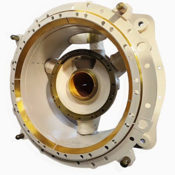
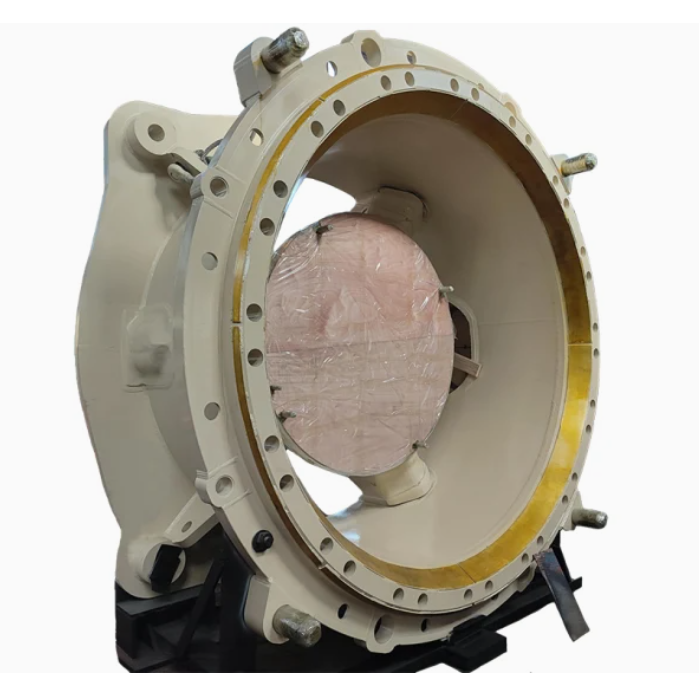
The cone crusher frame is typically a large, heavy-duty casting or welded structure with a complex shape, consisting of the following key components and structural details:
Frame Body: The main structure, usually a hollow box or cylindrical shape with a thick wall (80–200 mm), made of high-strength cast steel (e.g., ZG35CrMo) or welded low-alloy steel plates (e.g., Q355B).
Bearing Housing: A cylindrical recess at the bottom or top of the frame to accommodate the main shaft bearing, with a precision-machined inner surface (tolerance IT6) to ensure proper bearing fit.
Eccentric Bushing Chamber: A circular cavity in the middle of the frame where the eccentric bushing is installed, with a machined inner surface and oil grooves for lubrication.
Mounting Flanges:
Base Flange: A large flange at the bottom with bolt holes to secure the frame to the foundation, ensuring stability.
Upper Flange: A flange at the top to connect with the bowl or adjustment ring, often with guide pins or slots for alignment.
Reinforcing Ribs: Internal and external ribs (30–80 mm thick) arranged radially or axially to enhance the frame's rigidity and reduce deformation under load.
Lubrication and Cooling Channels: Drilled holes or cast passages for delivering lubricating oil to bearings and eccentric components, and for circulating cooling water in some large frames.
Inspection and Access Doors: Removable panels or doors for maintenance and inspection of internal components.
3. Casting Process for the Frame
For large and complex frame designs, sand casting is the preferred manufacturing method:
Material Selection:
High-strength cast steel (ZG35CrMo) is chosen for its excellent mechanical properties, including tensile strength (≥700 MPa), impact toughness (≥35 J/cm²), and good castability.
Pattern Making:
A full-scale pattern is made of wood, foam, or resin, replicating the frame's external shape, internal cavities, ribs, flanges, and other features. Shrinkage allowances (1.5–2.5%) are added based on the material and part size.
The pattern is reinforced to prevent deformation during molding, and cores are designed to form internal cavities and channels.
Molding:
A sand mold is prepared using resin-bonded sand, with the pattern placed in the mold. Cores are inserted to form the internal structure, ensuring accurate wall thickness and dimensional relationships between features.
The mold is coated with a refractory wash to improve surface finish and prevent metal penetration into the sand.
Melting and Pouring:
The cast steel is melted in an electric arc furnace at 1520–1560°C, with strict control of chemical composition (C: 0.32–0.40%, Cr: 0.8–1.1%, Mo: 0.15–0.25%).
Pouring is done at 1480–1520°C with a controlled flow rate to ensure complete filling of the mold cavity without turbulence, which could cause defects.
Cooling and Heat Treatment:
The casting is cooled slowly in the mold for 72–120 hours to reduce thermal stress, then removed and cleaned by shot blasting.
Heat treatment includes normalization (850–900°C, air-cooled) to refine the grain structure and tempering (600–650°C) to reduce hardness to 180–230 HBW, improving machinability.
4. Machining and Manufacturing Process
Rough Machining:
The cast frame is mounted on a large CNC boring mill or gantry mill to machine the base flange, upper flange, and external reference surfaces, leaving 5–10 mm finishing allowance.
Bearing Housing and Chamber Machining:
The bearing housing and eccentric bushing chamber are rough-bored, then finish-bored and honed to achieve high dimensional accuracy (tolerance IT6) and surface roughness (Ra0.8–1.6 μm).
Oil grooves are machined in the bearing housing and chamber using a CNC milling machine.
Flange and Mounting Surface Machining:
The base and upper flanges are finish-machined to ensure flatness (≤0.05 mm/m) and perpendicularity to the frame axis (≤0.1 mm/100 mm).
Bolt holes are drilled and tapped to precise positions (tolerance ±0.1 mm) using a CNC drilling machine.
Reinforcing Rib and External Surface Machining:
External ribs are machined to remove casting defects and ensure uniform dimensions.
The external surface is finish-machined to improve appearance and facilitate painting.
Surface Treatment:
The frame is painted with anti-rust primer and topcoat to resist corrosion.
Machined mounting surfaces and bearing fits are protected with anti-rust oil or grease.
5. Quality Control Processes
Material Testing:
Chemical composition analysis is performed to ensure compliance with the specified material standards.
Tensile testing and impact testing are conducted on test samples to verify mechanical properties.
Dimensional Inspection:
A coordinate measuring machine (CMM) is used to check critical dimensions, including the bearing housing diameter, flange flatness, and hole positions.
Laser scanning is employed to verify the overall shape and dimensions against the 3D model.
Non-Destructive Testing (NDT):
Ultrasonic testing (UT) is used to detect internal defects such as cracks and shrinkage in the frame body and ribs.
Magnetic particle testing (MPT) is performed on surface and near-surface areas, especially around bolt holes and stress concentration points.
Mechanical Testing:
Hardness testing is done to ensure the frame meets the required hardness range (180–230 HBW).
Load testing may be performed to verify the frame's ability to withstand design loads without excessive deformation.
Assembly and Functional Testing:
The frame is trial-assembled with key components such as the eccentric bushing and main shaft to ensure proper fit and alignment.
Vibration testing is conducted to check for excessive vibration during simulated operation.
Through these rigorous manufacturing and quality control processes, the cone crusher frame ensures the stability, reliability, and long service life of the entire crusher, making it suitable for heavy-duty crushing applications in mining, construction, and aggregate industries