The cone crusher socket, a key component at the moving cone's bottom, functions as a pivot for the main shaft, transmits loads to the frame, facilitates lubrication, and maintains alignment. It operates under high loads, requiring strength, wear resistance, and precision.
Structurally, it includes a high-strength alloy steel (42CrMo) body, a precision bearing cavity, eccentric bushing interface, lubrication channels, a mounting flange, and locating pins, with optional wear-resistant inserts.
Manufacturing involves sand casting (pattern making, molding, melting/pouring), heat treatment (quenching/tempering, local hardening), and machining (precision boring, flange processing, channel drilling).
Quality control covers material testing (composition, mechanics), dimensional checks (CMM, roundness testing), NDT (UT, MPT), mechanical tests (hardness, compression), and functional trials. These ensure it supports stable crusher operation in mining and aggregate processing.
Detailed Introduction to the Cone Crusher Socket Component
1. Function and Role of the Socket
The cone crusher socket (also known as the main shaft socket or eccentric socket) is a critical connecting component located at the bottom of the moving cone, serving as the pivot point for the main shaft. Its primary functions include:
Pivot Support: Providing a stable fulcrum for the main shaft, allowing it to swing eccentrically under the drive of the eccentric bushing, which is essential for generating the crushing motion.
Load Transmission: Transferring axial and radial loads from the moving cone and crushing process to the frame’s bottom bearing, ensuring force distribution across the crusher’s foundation.
Lubrication Interface: Housing lubrication channels that deliver oil to the main shaft’s lower bearing, reducing friction between the rotating shaft and stationary socket.
Alignment Maintenance: Maintaining the concentricity between the main shaft and eccentric bushing, preventing excessive vibration and uneven wear on mating components.
Operating under high static and dynamic loads, the socket requires high compressive strength, wear resistance, and dimensional precision to ensure stable crusher operation.
2. Composition and Structure of the Socket
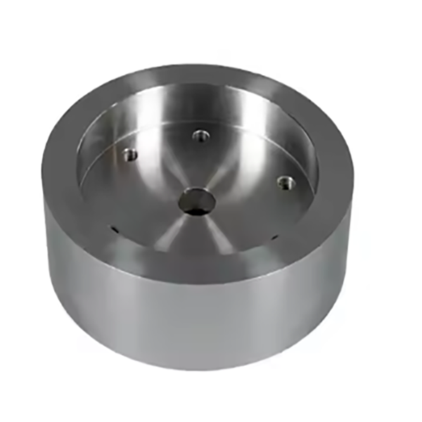
The socket is typically a cylindrical or conical component with a hollow center, featuring the following key parts and structural details:
Socket Body: A one-piece casting or forging made of high-strength alloy steel (e.g., 42CrMo) or high-chromium cast iron, with a diameter ranging from 150 mm to 600 mm depending on the crusher size. The body thickness is 30–80 mm to withstand heavy loads.
Bearing Cavity: A precision-machined central bore that houses the main shaft’s lower bearing (often a spherical roller bearing or sleeve bearing), with a surface roughness of Ra0.8 μm and dimensional tolerance IT6.
Eccentric Bushing Interface: An outer cylindrical or spherical surface that mates with the eccentric bushing, featuring a polished finish (Ra1.6 μm) to reduce friction during eccentric rotation.
Lubrication Channels: Radial and axial drilled holes (φ4–φ10 mm) that connect to the frame’s lubrication system, delivering oil to the bearing cavity and outer interface.
Mounting Flange: A radial flange at the base with bolt holes to secure the socket to the frame, ensuring it remains stationary during crusher operation. The flange has flatness tolerance ≤0.05 mm/m to prevent load concentration.
Locating Pins: Small cylindrical protrusions on the flange that fit into corresponding holes in the frame, ensuring precise radial positioning of the socket.
Wear-Resistant Insert (Optional): A replaceable bronze or babbitt metal sleeve pressed into the bearing cavity, enhancing wear resistance and allowing easy replacement without replacing the entire socket.
3. Casting Process for the Socket
For most socket designs, sand casting is the primary manufacturing method due to the component’s complex geometry:
Material Selection:
High-strength alloy steel (42CrMo) is preferred for its excellent tensile strength (≥1080 MPa), yield strength (≥930 MPa), and impact toughness (≥60 J/cm²). Chemical composition is controlled to C 0.38–0.45%, Cr 0.9–1.2%, Mo 0.15–0.25%.
Pattern Making:
A full-scale pattern (foam, wood, or resin) is created, replicating the socket’s outer shape, bearing cavity, flange, and lubrication channel positions. Shrinkage allowances (1.5–2.0%) are added to account for cooling contraction.
Molding:
A resin-bonded sand mold is prepared, with a sand core used to form the central bearing cavity. The mold is coated with a refractory wash to improve surface finish and prevent sand inclusion.
Melting and Pouring:
The alloy steel is melted in an induction furnace at 1520–1560°C, with strict control of sulfur and phosphorus content (≤0.035% each) to avoid brittleness.
Pouring is performed at 1480–1520°C with a controlled flow rate to ensure complete filling of the mold cavity, minimizing porosity in critical areas like the bearing cavity.
Heat Treatment:
Quenching and Tempering: The casting is heated to 850–880°C, held for 2–3 hours, then quenched in oil. Tempering at 550–600°C for 4–5 hours achieves a hardness of HRC 28–35, balancing strength and machinability.
Local Hardening: The bearing cavity surface is induction-hardened to a depth of 2–4 mm, achieving HRC 50–55 to enhance wear resistance.
4. Machining and Manufacturing Process
Rough Machining:
The cast blank is mounted on a CNC lathe to machine the outer surface, flange, and preliminary bearing cavity, leaving 2–3 mm finishing allowance. Key dimensions (e.g., flange diameter) are controlled to ±0.5 mm.
Precision Machining of Bearing Cavity:
The central bore is finish-bored and honed to achieve dimensional tolerance IT6 (e.g., φ200H6) and surface roughness Ra0.8 μm, ensuring proper bearing fit. Roundness is controlled to ≤0.005 mm.
Flange and Mounting Feature Machining:
The mounting flange is finish-machined to flatness (≤0.05 mm/m) using a CNC grinder. Bolt holes are drilled and tapped to class 6H tolerance, with positional accuracy (±0.1 mm) relative to the socket axis.
Lubrication Channel Drilling:
Axial and radial oil holes are drilled using CNC deep-hole drilling machines, with strict positional tolerance (±0.2 mm) to ensure unobstructed oil flow. Hole intersections are deburred to prevent oil flow disruption.
Surface Treatment:
The bearing cavity is polished to Ra0.4 μm to reduce friction and improve bearing life.
The outer surface and flange are coated with anti-rust paint, while the mounting surface is treated with anti-seize compound for easy installation.
5. Quality Control Processes
Material Testing:
Chemical composition analysis (spectrometry) verifies compliance with 42CrMo standards.
A coordinate measuring machine (CMM) inspects critical dimensions: bearing cavity diameter, flange flatness, and bolt hole positions.
A roundness tester measures the bearing cavity’s roundness and cylindricity, ensuring values ≤0.005 mm.
Non-Destructive Testing (NDT):
Ultrasonic testing (UT) detects internal defects in the socket body, with any cracks or pores >φ2 mm resulting in rejection.
Magnetic particle testing (MPT) checks for surface cracks in the flange, bolt holes, and bearing cavity, with linear defects >0.2 mm rejected.
Mechanical Property Testing:
Hardness testing (Rockwell) ensures the bearing cavity has HRC 50–55 and the core has HRC 28–35.
Compressive strength testing on samples verifies the socket can withstand axial loads ≥200 MPa.
Functional Testing:
A trial fit with the main shaft and bearing confirms proper assembly: the shaft rotates smoothly without binding, and lubricant flows freely through the channels.
Load testing applies 120% of rated axial load for 1 hour, with post-test inspection showing no deformation (bearing cavity diameter change ≤0.01 mm).
Through these manufacturing and quality control processes, the cone crusher socket achieves the strength, precision, and reliability required to support the main shaft and facilitate stable crushing motion, ensuring efficient operation in mining and aggregate processing applications