The cone crusher clamping ring, a key fastening component between the adjustment ring and lower frame, secures the concave and stabilizes the bowl assembly. It fixes the concave, locks adjustments, distributes loads, and enhances sealing, enduring high clamping forces and cyclic loads.
Structurally, it includes a high-strength cast/forged steel ring body, precision clamping surface, bolt holes, lifting lugs, locating features, and reinforcement ribs, with optional wear-resistant coatings.
Manufacturing involves sand casting (ZG35CrMo) or forging (35CrMo), followed by heat treatment, machining (CNC turning/grinding for precision), and surface treatment.
Quality control covers material testing (composition, mechanics), dimensional checks (CMM, laser tracking), structural integrity tests (UT, MPT), mechanical performance trials (clamping force, fatigue), and assembly validation. These ensure it reliably secures components for consistent crusher operation in mining and aggregate processing.
Detailed Introduction to the Cone Crusher Clamping Ring Component
1. Function and Role of the Clamping Ring
The cone crusher clamping ring (also known as the lock ring or bowl clamping ring) is a critical fastening component located between the adjustment ring and the lower frame, primarily responsible for securing the concave (fixed cone liner) and maintaining the stability of the bowl assembly. Its key functions include:
Concave Fixation: Applying radial and axial pressure to clamp the concave segments tightly against the bowl’s inner surface, preventing displacement or vibration during crushing, which could lead to uneven wear or material leakage.
Adjustment Locking: Securing the adjustment ring in its set position after gap adjustments, ensuring the crushing gap remains consistent during operation and avoiding unintended changes that affect product size.
Load Transfer: Distributing the clamping force evenly across the concave and bowl, reducing localized stress concentrations and extending the service life of mating components.
Sealing Enhancement: Creating a tight seal between the adjustment ring and lower frame, minimizing the ingress of dust, ore particles, and moisture into internal mechanisms, thus reducing wear and lubricant contamination.
Operating under high clamping forces (often exceeding 100 kN) and cyclic loads, the clamping ring requires high tensile strength, rigidity, and wear resistance to maintain its clamping capability over extended periods.
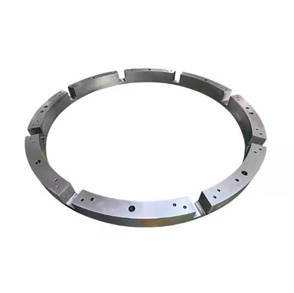
2. Composition and Structure of the Clamping Ring
The clamping ring is typically an annular, one-piece or segmented component with a robust design, featuring the following key parts and structural details:
Ring Body: A circular frame made of high-strength cast steel (e.g., ZG35CrMo) or forged steel, with an outer diameter ranging from 800 mm to 3000 mm depending on the crusher size. The body thickness is 40–100 mm, with a radial width of 100–300 mm to withstand clamping forces.
Clamping Surface: A precision-machined, inclined or flat surface on the inner circumference that interfaces with the concave’s outer flange or the adjustment ring. This surface has a roughness of Ra1.6–3.2 μm to ensure uniform force distribution.
Threaded Holes/Bolt Slots: Circumferentially spaced holes (12–36, depending on size) or elongated slots that accommodate clamping bolts. These are positioned to apply even pressure, with hole diameter tolerance H12 and positional accuracy (±0.5 mm) relative to the ring’s center.
Lifting Lugs: Integrally cast or welded protrusions on the outer surface to facilitate installation and removal using lifting equipment, designed to withstand the ring’s weight (often 500–5000 kg).
Locating Features:
Alignment Pins: Small cylindrical protrusions on the lower surface that fit into corresponding holes in the lower frame, ensuring radial positioning.
Grooves/Notches: Circumferential grooves that mate with ribs on the adjustment ring, preventing rotational slippage under load.
Reinforcement Ribs: Radial or circumferential ribs on the outer or inner surface that enhance rigidity without excessive weight, positioned to resist deformation under clamping pressure.
Wear-Resistant Coating (Optional): A hard chromium plating (50–100 μm thick) or weld overlay on the clamping surface to reduce wear from repeated contact with the concave or adjustment ring.
3. Casting Process for the Clamping Ring
Given its large size and annular structure, the clamping ring is primarily manufactured via sand casting, with forged steel used for high-load applications:
Material Selection:
Cast Steel (ZG35CrMo): Preferred for its balance of strength (tensile strength ≥650 MPa, yield strength ≥380 MPa) and castability. Chemical composition: C 0.32–0.40%, Cr 0.8–1.1%, Mo 0.15–0.25%.
Forged Steel (35CrMo): Used for crushers with extreme loads, offering higher toughness (impact energy ≥40 J) and fatigue resistance.
Pattern Making:
A full-scale pattern is created using 3D-printed resin, wood, or foam, replicating the ring’s outer diameter, width, bolt holes, and lugs. Shrinkage allowances (1.8–2.2%) are added, with larger allowances for thick sections like ribs.
Molding:
A resin-bonded sand mold is prepared with split patterns to form the annular shape. Cores are used to create bolt holes and internal features, ensuring dimensional consistency. The mold cavity is coated with a zirconium-based refractory wash to improve surface finish.
Melting and Pouring:
Cast steel is melted in an electric arc furnace at 1530–1570°C, with strict control of sulfur (≤0.035%) and phosphorus (≤0.035%) to avoid brittleness.
Pouring is performed at 1490–1530°C using a ladle with a tundish to control flow, ensuring the mold fills evenly and minimizes porosity in critical areas like bolt hole bosses.
Heat Treatment:
Normalization: Heating to 860–900°C for 3–5 hours, followed by air cooling to refine the grain structure and reduce internal stress.
Tempering: Heating to 550–600°C for 4–6 hours to achieve a hardness of HB 200–250, balancing strength and machinability. For forged rings, quenching (850–880°C, oil-cooled) plus tempering is used to enhance toughness.
4. Machining and Manufacturing Process
Rough Machining:
The cast or forged ring is mounted on a CNC vertical lathe to machine the outer diameter, inner diameter, and top/bottom surfaces, leaving 3–5 mm finishing allowance. Key dimensions (e.g., outer diameter) are controlled to ±1 mm.
Clamping Surface Finishing:
The inner clamping surface is precision-machined using a CNC turning center or grinder to achieve flatness (≤0.1 mm/m) and roughness Ra1.6 μm. Inclined surfaces (if present) are cut to an angle tolerance of ±0.1°.
Bolt Hole Machining:
Threaded holes or slots are drilled and tapped using a CNC machining center with a rotary table, ensuring positional accuracy (±0.5 mm) and thread quality (class 6H for tapped holes). Hole bosses are reinforced to prevent stripping under high torque.
Lifting Lug and Feature Machining:
Lifting lugs are machined to remove casting flash and ensure safe lifting, with radiused edges to reduce stress concentration.
Locating pins or grooves are milled to precise dimensions, with tolerance ±0.1 mm for alignment features.
Surface Treatment:
The clamping surface is optionally coated with hard chromium (50–100 μm) via electroplating, achieving a hardness of HRC 60–65 to resist wear.
Non-mating surfaces are blast-cleaned and painted with epoxy paint (100–150 μm thick) to resist corrosion.
5. Quality Control Processes
Material Testing:
Chemical composition analysis (spectrometry) verifies compliance with ZG35CrMo or 35CrMo standards.
A coordinate measuring machine (CMM) inspects critical dimensions: outer/inner diameter, clamping surface flatness, and bolt hole positions.
A laser tracker verifies the ring’s circularity (≤0.2 mm) and concentricity between inner and outer diameters (≤0.1 mm).
Structural Integrity Testing:
Ultrasonic testing (UT) detects internal defects in the ring body and bolt hole bosses, with any cracks or pores >φ3 mm rejected.
Magnetic particle testing (MPT) checks for surface cracks in lugs, clamping surfaces, and bolt holes, with linear defects >1 mm resulting in rejection.
Mechanical Performance Testing:
Clamping Force Test: The ring is installed with bolts torqued to 120% of rated value, with strain gauges measuring deformation (limit: ≤0.2 mm/m).
Fatigue Testing: Samples undergo cyclic loading (10⁶ cycles) at 80% of yield strength to ensure no cracking, simulating long-term use.
Assembly Validation:
Trial assembly with the adjustment ring and concave segments verifies proper fit: clamping force is evenly distributed, and there is no excessive clearance between mating surfaces.
Through these manufacturing and quality control processes, the clamping ring ensures secure fixation of the concave and stable operation of the cone crusher, making it essential for consistent performance in mining and aggregate processing applications