The cone crusher dust shell, a protective component at the crusher's upper part, prevents dust, debris, and moisture from entering internal parts (e.g., adjustment gear, thrust bearing), enhances safety by blocking access to moving components, and reduces noise. It operates in harsh, dusty environments, requiring durability and a tight seal.
Structurally, it includes a thin-walled shell body (mild steel, stainless steel, or cast iron), upper/lower flanges with seals, reinforcement ribs, inspection doors, optional ventilation holes, and lifting lugs.
Manufacturing processes vary by material: mild/stainless steel shells undergo cutting, rolling, welding, and finishing; cast iron shells use sand casting and heat treatment. Machining focuses on flange flatness and seal surfaces, with surface treatments like painting or passivation.
Quality control involves material testing, dimensional checks, structural integrity tests (weld inspection, pressure testing), functional tests (seal performance, impact resistance), and assembly validation. These ensure the dust shell reliably protects internal components, supporting the crusher's efficient operation
Detailed Introduction to the Cone Crusher Dust Shell Component
1. Function and Role of the Dust Shell
The cone crusher dust shell (also called the dust cover or protective shell) is a critical protective component installed at the upper part of the crusher, surrounding the adjustment ring, clamping ring, and the gap between the moving cone and concave. Its primary functions include:
Contamination Prevention: Blocking dust, ore particles, and debris generated during crushing from entering internal components such as the adjustment gear, thrust bearing, and lubrication system, thereby reducing wear and extending maintenance intervals.
Moisture Protection: Shielding sensitive parts from rain, groundwater, or process water, preventing corrosion of metal surfaces and degradation of lubricants.
Safety Enhancement: Acting as a physical barrier to prevent operators or foreign objects from contacting rotating or moving parts (e.g., the adjustment ring), reducing the risk of accidents.
Noise Reduction: Dampening high-frequency noise generated by material impact and component friction, contributing to a safer working environment.
Operating in a harsh, dusty environment with constant exposure to abrasive particles, the dust shell requires durability, impact resistance, and a tight seal to fulfill its protective role effectively.
2. Composition and Structure of the Dust Shell
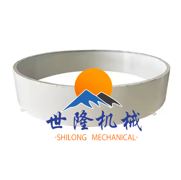
The dust shell is typically a cylindrical or conical shell with a flanged design, featuring the following key components and structural details:
Shell Body: A thin-walled (3–8 mm thick) annular or conical structure made of mild steel (Q235), stainless steel (304), or wear-resistant cast iron (HT250). Its diameter ranges from 600 mm to 2500 mm, matching the crusher’s upper dimensions.
Upper Flange: A radial flange at the top edge, bolted to the concave retainer or bowl, with a rubber or felt gasket to ensure a dust-tight seal. The flange has evenly spaced bolt holes (8–24) with positional tolerance (±1 mm).
Lower Flange: A radial flange at the bottom edge, connected to the lower frame or adjustment ring, often with a labyrinth seal or flexible lip seal to accommodate minor axial movement while blocking dust.
Reinforcement Ribs: Circumferential or axial ribs welded or cast onto the inner/outer surface to enhance rigidity, preventing deformation under wind loads or accidental impacts.
Inspection Doors: Removable panels (1–2) with quick-release latches, allowing visual inspection of internal components without full disassembly. These doors are fitted with gaskets to maintain the seal.
Ventilation Holes (Optional): Small holes (φ5–10 mm) with mesh screens to equalize pressure inside and outside the shell, preventing vacuum or pressure buildup that could damage the seal.
Lifting Lugs: Small welded or cast protrusions for safe installation and removal, designed to support the shell’s weight (typically 50–300 kg).
3. Manufacturing Process for the Dust Shell
Depending on the material, the dust shell is produced using rolling, casting, or welding processes:
Material Selection: Mild steel (Q235) is used for general applications (cost-effective, easy to weld), while stainless steel (304) is chosen for corrosive environments (moist or coastal settings).
Plate Cutting: Steel plates are cut to the required size using plasma cutting or laser cutting, with dimensional tolerance (±2 mm) for the blank.
Rolling/Forming: The plate is rolled into a cylindrical or conical shape using a plate rolling machine, with the seam welded via MIG (metal inert gas) welding. Welds are ground smooth to ensure a uniform surface.
Flange Fabrication: Flanges are cut from steel plate, rolled (for circular flanges), and welded to the shell body. Welds are inspected for penetration and strength.
Rib Installation: Reinforcement ribs (cut from angle iron or flat bar) are welded to the shell at intervals of 200–500 mm, with fillet welds to ensure structural integrity.
3.2 Cast Iron Shells (Heavy-Duty Applications)
Material Selection: Wear-resistant cast iron (HT250) is used for high-impact environments, offering good rigidity and abrasion resistance (tensile strength ≥250 MPa).
Sand Casting: A sand mold is created using a pattern of the shell, with cores for bolt holes and inspection ports. Molten iron (1380–1420°C) is poured into the mold, then cooled and shaken out.
Heat Treatment: Annealing at 550–600°C relieves casting stress, reducing the risk of cracking during machining.
4. Machining and Finishing
Flange Machining: Flanges are machined on a lathe or milling machine to achieve flatness (≤0.5 mm/m) and ensure proper gasket seating. Bolt holes are drilled and deburred to prevent gasket damage.
Seal Surface Preparation: The mating surfaces of upper and lower flanges are ground or sandblasted to a roughness of Ra3.2–6.3 μm, ensuring compatibility with gaskets or labyrinth seals.
Inspection Door Fitting: Door frames are welded to the shell, with hinge pins and latches installed. Door edges are machined to ensure a tight fit with the frame.
Surface Treatment:
Mild steel shells are painted with anti-rust primer (60–80 μm) and topcoat (40–60 μm) to resist corrosion.
Stainless steel shells are passivated to enhance their oxide layer, improving corrosion resistance.
Cast iron shells are coated with enamel or epoxy paint for protection.
5. Quality Control Processes
Material Testing:
Chemical composition analysis (spectrometry) verifies steel or cast iron compliance (e.g., Q235: C ≤0.22%, Mn 0.3–0.65%).
A tape measure or laser scanner verifies overall diameter and height, with tolerance (±5 mm) for large shells.
A straightedge and feeler gauge check flange flatness, ensuring values ≤0.5 mm/m.
Structural Integrity Testing:
Weld Inspection: For steel shells, welds are inspected via visual examination and dye penetrant testing (DPT) to detect cracks or porosity.
Pressure Testing: The assembled shell (with flanges sealed) is pressurized to 0.1 MPa with air, with no pressure drop over 30 minutes indicating a tight seal.
Functional Testing:
Seal Performance: The shell is installed on a test fixture, and compressed air with talc powder is applied externally; no powder penetration into the interior is allowed.
Impact Resistance: A 5 kg steel ball is dropped from 1 m onto the shell surface, with no visible deformation or cracking required.
Assembly Validation:
Trial installation on the crusher confirms proper alignment with the bowl, adjustment ring, and lower frame, with all bolts fitting into their respective holes without force.
Through these manufacturing and quality control processes, the dust shell effectively protects internal components from contamination, ensuring reliable operation of the cone crusher in demanding industrial environments