The cone crusher thrust bearing, a key component handling axial loads (up to thousands of kilonewtons) at the main shaft bottom or between the adjustment ring and frame, supports vertical forces, enables smooth rotation, maintains alignment, and integrates with lubrication systems. It operates at 500–1500 rpm, demanding high strength and precision.
Composed of a 42CrMo thrust collar (HRC 50–55 surface), babbitt/bronze thrust pads, a cast iron/steel housing, lubrication elements, locating devices, and seals, it forms a robust assembly.
Manufacturing involves forging and heat-treating the collar, casting/bonding babbitt to steel for pads, and sand-casting the housing, followed by precision machining. Assembly includes pad installation, lubrication integration, and alignment checks.
Quality control covers material testing, dimensional inspection, NDT (UT, MPT), performance trials (load, friction), and lubrication validation. These ensure reliable operation in mining and aggregate processing.
Detailed Introduction to the Cone Crusher Thrust Bearing Component
1. Function and Role of the Thrust Bearing
The cone crusher thrust bearing is a critical load-bearing component located at the bottom of the main shaft or between the adjustment ring and frame, designed to withstand axial loads generated during the crushing process. Its primary functions include:
Axial Load Support: Absorbing vertical forces (up to thousands of kilonewtons) from the moving cone, main shaft, and material crushing, preventing axial displacement of key components.
Rotation Facilitation: Allowing smooth rotation of the main shaft or adjustment ring while maintaining axial stability, reducing friction and energy loss.
Alignment Maintenance: Ensuring the main shaft remains concentric with the frame, preventing misalignment that could cause uneven wear on the mantle, concave, or other components.
Lubrication Integration: Working with the lubrication system to distribute oil evenly across contact surfaces, minimizing wear and heat generation under high loads.
Operating in a high-load, high-speed environment (500–1500 rpm), the thrust bearing requires exceptional compressive strength, wear resistance, and dimensional precision to ensure long-term reliability.
2. Composition and Structure of the Thrust Bearing
The thrust bearing is typically a multi-component assembly consisting of rotating and stationary parts, with the following key components:
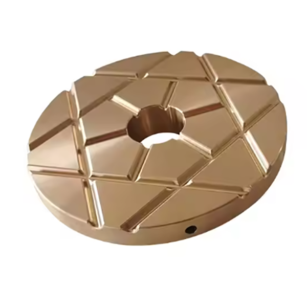
Thrust Collar (Rotating Element): A disk-shaped component attached to the main shaft, featuring a precision-machined thrust surface (Ra0.8–1.6 μm) that contacts the bearing pads. It is made of high-strength alloy steel (e.g., 42CrMo) with a hardened surface (HRC 50–55).
Thrust Pads (Stationary Elements): Segmented or full-circle pads (3–8 pieces) that bear axial loads against the thrust collar. They are made of babbitt metal (tin-based: Sn 83–85%, Sb 11–13%), bronze (ZCuSn10Pb1), or steel-backed bimetallic materials with a wear-resistant overlay.
Bearing Housing: A cylindrical or annular casing that holds the thrust pads in place, mounted to the frame or adjustment ring. It is made of cast iron (HT300) or cast steel (ZG270-500) and features oil grooves for lubricant distribution.
Lubrication System:
Oil Inlet/Outlet Ports: Channels in the housing that deliver pressurized lubricant (mineral oil or synthetic grease) to the contact surfaces between the collar and pads.
Oil Grooves: Circumferential or radial grooves in the bearing housing or pad surfaces to ensure uniform oil distribution and prevent dry friction.
Locating Pins/Clips: Devices that secure the thrust pads in the housing, preventing rotation or displacement under load.
Sealing Elements: O-rings or labyrinth seals that prevent lubricant leakage and block contamination from dust, water, or ore particles.
3. Manufacturing Processes for Key Components
3.1 Thrust Collar (Alloy Steel)
Material Selection: High-strength alloy steel (42CrMo) is chosen for its excellent tensile strength (≥1080 MPa) and impact toughness (≥60 J/cm²).
Forging: The steel billet is heated to 1100–1200°C and forged into a disk shape via open-die forging, refining the grain structure and eliminating internal defects.
Heat Treatment: Quenching (850–880°C, oil-cooled) followed by tempering (550–600°C) achieves a core hardness of HRC 28–35. The thrust surface is induction-hardened to HRC 50–55 for wear resistance.
Machining: CNC turning and grinding processes achieve flatness (≤0.01 mm/m) and surface roughness (Ra0.8 μm) on the thrust surface, with dimensional tolerance (±0.02 mm) for outer diameter.
3.2 Thrust Pads (Babbitt Metal)
Material Selection: Tin-based babbitt metal (Sn-Sb-Cu alloy) is used for its low friction coefficient (≤0.1) and excellent conformability to minor misalignments.
Casting: Babbitt metal is cast onto a steel backing plate (Q235) via centrifugal casting or gravity casting, forming a 2–5 mm thick overlay. The steel backing is pre-cleaned and roughened to ensure metallurgical bonding.
Machining: The pad surface is ground to achieve flatness (≤0.02 mm/m) and surface roughness (Ra1.6 μm). Grooves for lubrication are milled into the surface with precise depth (0.5–1 mm).
3.3 Bearing Housing (Cast Iron)
Material Selection: Gray cast iron (HT300) is selected for its good vibration damping and machinability, with a tensile strength of ≥300 MPa.
Sand Casting: A resin-bonded sand mold is used to cast the housing, with cores forming oil channels and mounting features. Pouring temperature is 1380–1420°C.
Heat Treatment: Annealing at 550–600°C relieves casting stress, reducing the risk of deformation during machining.
Machining: CNC milling and drilling processes create mounting holes, oil ports, and pad recesses, with dimensional tolerance (±0.1 mm) for critical features.
4. Assembly and Finishing
Thrust Pad Installation: Pads are pressed into the housing recesses with a slight interference fit (0.01–0.03 mm) and secured with locating pins.
Lubrication System Integration: Oil channels are cleaned and tested for flow, with seals installed to prevent leakage.
Thrust Collar Alignment: The collar is mounted on the main shaft and checked for perpendicularity to the shaft axis (≤0.05 mm/m) using a dial indicator.
Run-Out Testing: The assembled bearing is rotated under no-load conditions to measure radial and axial run-out, ensuring values ≤0.05 mm.
5. Quality Control Processes
Material Testing: Chemical composition analysis (spectrometry) verifies alloy compliance (e.g., 42CrMo, HT300). Hardness testing (Rockwell/Brinell) confirms surface and core hardness meet specifications.
Dimensional Inspection: Coordinate measuring machines (CMM) check critical dimensions of the collar, pads, and housing, ensuring compliance with tolerances. Flatness and parallelism are verified using optical flats.
Non-Destructive Testing (NDT):
Ultrasonic testing (UT) detects internal defects in the thrust collar (e.g., cracks, inclusions).
Magnetic particle testing (MPT) inspects the collar’s thrust surface for surface cracks.
Bond testing (ultrasonic or peel tests) ensures babbitt-to-steel bonding in thrust pads (no delamination).
Performance Testing:
Load testing applies 120% of rated axial load for 1 hour, monitoring temperature rise (≤40°C above ambient) and wear (≤0.01 mm).
Friction testing measures the coefficient of friction under simulated operating conditions, requiring values ≤0.15 with proper lubrication.
Lubrication Validation: Pressure testing of oil channels ensures no blockages, with flow rates verified to meet design specifications.
Through these rigorous manufacturing and quality control processes, the cone crusher thrust bearing reliably supports axial loads, ensures smooth rotation, and extends the service life of the crusher, making it essential for efficient operation in mining and aggregate processing