The cone crusher adapter ring, a key component between the main shaft and moving cone, transmits torque and axial loads, compensates for minor misalignment, protects high-cost parts, and eases assembly. It operates under high torque and cyclic loads, demanding strength and precision.
Structurally, it features a tapered alloy steel (40CrNiMoA or 45#) body with a precision inner taper (1:10 to 1:20), outer threads/flange, keyway, lubrication grooves, and a positioning shoulder.
Manufacturing involves forging (heating to 1150–1200°C, upsetting/piercing) or casting, followed by quenching/tempering (HRC 28–35). Machining includes precision grinding of the taper (Ra0.8 μm) and threading.
Quality control covers material testing (composition, tensile/impact strength), dimensional checks (CMM, taper gauge), NDT (UT, MPT), torque/fatigue testing, and assembly validation. These ensure reliable performance in torque/load transmission for efficient crusher operation.
Detailed Introduction to the Cone Crusher Adapter Ring Component
1. Function and Role of the Adapter Ring
The cone crusher adapter ring (also known as the transition ring or coupling ring) is a key connecting component located between the main shaft and the moving cone, serving as a mechanical interface to transmit torque and axial loads. Its primary functions include:
Load Transmission: Transferring rotational force from the eccentric bushing to the moving cone, ensuring synchronized motion during crushing. It also distributes axial loads from the moving cone to the main shaft, preventing stress concentration at the connection point.
Alignment Compensation: Allowing minor misalignment between the main shaft and moving cone (up to 0.1 mm) due to manufacturing tolerances or operational wear, reducing vibration and extending component life.
Wear Protection: Acting as a replaceable intermediary to protect the main shaft and moving cone from direct contact, minimizing wear on these high-cost components.
Assembly Facilitation: Simplifying the installation and replacement of the moving cone by providing a standardized connection interface, reducing maintenance time.
Operating under high torque (up to thousands of N·m) and cyclic loads, the adapter ring requires high tensile strength, fatigue resistance, and dimensional precision to ensure reliable performance.
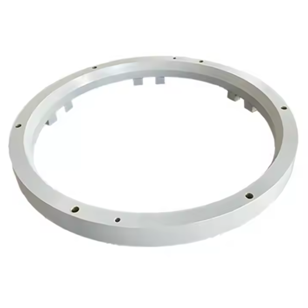
2. Composition and Structure of the Adapter Ring
The adapter ring is typically an annular, tapered component with a hollow center, featuring the following key parts and structural details:
Ring Body: A one-piece forging or casting made of high-strength alloy steel (e.g., 40CrNiMoA) or medium-carbon steel (45#), with an outer diameter ranging from 300 mm to 1200 mm. The wall thickness is 20–50 mm, with a tapered inner surface to match the main shaft.
Tapered Inner Surface: A precision-machined conical surface (taper ratio 1:10 to 1:20) that mates with the main shaft’s tapered end, ensuring a tight interference fit (0.02–0.05 mm) to transmit torque without slippage. Surface roughness is Ra0.8–1.6 μm.
Outer Threads/Flange: An externally threaded section or radial flange on the upper end that connects to the moving cone, with thread class 6g or flange flatness (≤0.05 mm/m) for secure fastening.
Keyway/Keyseat: A longitudinal slot or recess on the inner surface that accommodates a key, enhancing torque transmission between the adapter ring and main shaft. Keyway dimensions follow standard ISO 4156 (e.g., width tolerance H9).
Lubrication Grooves: Circumferential grooves on the tapered inner surface that distribute lubricant during assembly/disassembly, reducing friction when installing or removing the ring.
Shoulder: A radial step at the lower end that limits axial movement, ensuring the adapter ring is positioned correctly on the main shaft. The shoulder has perpendicularity tolerance (≤0.03 mm/100 mm) relative to the inner taper.
Marking Grooves: Small recesses or laser-etched marks indicating the orientation or weight for balanced assembly, critical for high-speed operation.
3. Manufacturing Process for the Adapter Ring
Given its high load requirements, the adapter ring is primarily manufactured via forging, with casting used for smaller, lower-load applications:
Material Selection:
Alloy Steel (40CrNiMoA): Preferred for large crushers, offering tensile strength ≥980 MPa, yield strength ≥835 MPa, and impact toughness ≥60 J/cm². Chemical composition: C 0.37–0.44%, Cr 0.6–0.9%, Ni 1.2–1.6%, Mo 0.15–0.25%.
Medium-Carbon Steel (45#): Used for smaller rings, with tensile strength ≥600 MPa and yield strength ≥355 MPa.
Forging:
The steel billet is heated to 1150–1200°C and forged into a cylindrical or conical preform using open-die forging, refining the grain structure and improving mechanical properties.
Upsetting and piercing processes create the hollow center, with rough shaping of the outer diameter and taper.
Heat Treatment:
Quenching and Tempering: Forged blanks are heated to 820–860°C, quenched in oil, then tempered at 500–600°C for 4–6 hours to achieve hardness HRC 28–35, balancing strength and machinability.
Stress Relieving: After rough machining, a low-temperature annealing (300–350°C for 2 hours) relieves residual stresses from forging and machining.
Casting (for Small Rings):
Sand casting with resin-bonded molds is used for low-volume production. Molten steel is poured at 1500–1550°C, followed by normalization to refine the microstructure.
4. Machining and Manufacturing Process
Rough Machining:
The forged or cast blank is mounted on a CNC lathe to machine the outer diameter, inner taper (leaving 1–2 mm allowance), and shoulder, with dimensional tolerance (±0.5 mm).
Precision Machining:
Tapered Inner Surface: Ground using a CNC taper grinder to achieve the specified taper ratio (tolerance ±0.01 mm/m) and surface roughness Ra0.8 μm. Roundness is controlled to ≤0.01 mm.
Outer Threads/Flange: Threads are cut using a CNC thread lathe (tolerance 6g), while flanges are ground to flatness (≤0.05 mm/m) and perpendicularity (≤0.03 mm/100 mm).
Keyway: Milled using a CNC milling machine with width tolerance H9 and depth tolerance (±0.1 mm), ensuring proper key fit.
Lubrication Groove Machining:
Grooves are turned or milled into the inner taper with precise depth (0.5–1 mm) and spacing (50–100 mm), facilitating lubricant distribution.
Surface Treatment:
The outer surface is shot-blasted to remove scale, then coated with anti-rust oil or paint. The inner tapered surface may be phosphate-coated to improve lubricity during assembly.
5. Quality Control Processes
Material Testing:
Chemical composition analysis (spectrometry) verifies alloy compliance (e.g., 40CrNiMoA).
Tensile and impact testing on forged samples confirm mechanical properties (tensile strength ≥980 MPa, impact energy ≥60 J).
Dimensional Accuracy Checks:
A coordinate measuring machine (CMM) inspects the taper ratio, inner/outer diameters, and keyway dimensions, ensuring compliance with tolerances.
A taper gauge and dial indicator verify the inner taper’s conformity to design specifications.
Non-Destructive Testing (NDT):
Ultrasonic testing (UT) detects internal defects in the ring body, with any cracks or inclusions >φ2 mm rejected.
Magnetic particle testing (MPT) checks for surface cracks in threads, keyways, and shoulders, with linear defects >0.5 mm resulting in rejection.
Mechanical Performance Testing:
Torque Testing: The ring is assembled with a test shaft and subjected to 120% of rated torque, with no slippage or deformation allowed.
Fatigue Testing: Samples undergo cyclic loading (10⁶ cycles) at 70% of yield strength to ensure resistance to fatigue failure.
Assembly Validation:
Trial assembly with a main shaft and moving cone confirms proper fit: the ring seats fully without binding, and torque transmission is smooth under test loads.
Through these manufacturing and quality control processes, the adapter ring ensures reliable torque and load transmission between the main shaft and moving cone, contributing to the efficient and stable operation of the cone crusher