Detailed Introduction to the Cone Crusher Head Ball Component
1. Function and Role of the Head Ball
The cone crusher head ball (also referred to as the main shaft head or upper pivot ball) is a critical load-bearing and positioning component located at the top of the moving cone assembly. Its primary functions include:
Operating under high contact stress (often exceeding 500 MPa) and cyclic loads, the head ball requires exceptional hardness, compressive strength, and fatigue resistance to maintain performance over extended service intervals.
2. Composition and Structure of the Head Ball
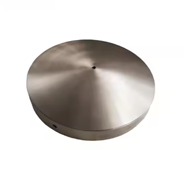
The head ball is typically a spherical or hemispherical component integrated with the moving cone shaft, featuring the following key parts and structural details:
Ball Head: A hemispherical or spherical tip with a radius ranging from 50 mm to 300 mm, depending on the crusher size. It is made of high-carbon chromium bearing steel (e.g., GCr15) or alloy steel (42CrMo) with a hardened surface (HRC 58–62).
Hardened Layer: A 2–5 mm deep case-hardened layer on the ball head surface, achieved via carburizing or induction hardening, to balance wear resistance (surface HRC 58–62) with core toughness (HRC 25–35).
3. Casting and Forging Processes for the Head Ball
Given its high-stress requirements, the head ball is primarily manufactured via forging, with casting used only for low-load, small-scale applications:
3.1 Forging Process (Primary Method)
Material Selection: High-carbon chromium bearing steel (GCr15) is preferred for its excellent wear resistance and fatigue life. Chemical composition: C 0.95–1.05%, Cr 1.3–1.65%, Mn ≤0.4%, Si ≤0.35%.
3.2 Casting Process (Secondary Method)
Investment Casting: For complex geometries, wax patterns are used to create ceramic molds. Molten steel (1520–1560°C) is poured into the molds, producing near-net-shape components with minimal machining required.
4. Machining and Heat Treatment Processes
The forged or cast blank is mounted on a CNC lathe to machine the shaft neck, transition fillet, and preliminary ball head shape, leaving 1–2 mm finishing allowance.
Quenching and Tempering: For GCr15, the blank is heated to 830–860°C, quenched in oil, then tempered at 150–200°C to achieve core hardness HRC 25–35.
5. Quality Control Processes
A coordinate measuring machine (CMM) inspects the ball head’s spherical radius, shaft neck diameter, and transition fillet, ensuring tolerances are within ±0.01 mm for critical features.
Through these rigorous manufacturing and quality control processes, the head ball ensures reliable load support, smooth rotation, and long service life, making it essential for the efficient operation of cone crushers in mining and aggregate processing