The cone crusher socket liner, a replaceable wear-resistant component in the socket’s bearing cavity, acts as an interface between the rotating main shaft and stationary socket. It protects against wear, reduces friction (≤0.15 with lubrication), distributes loads, and compensates for minor misalignment, requiring good wear resistance and lubricant compatibility.
Structurally, it is a cylindrical/flanged sleeve with a liner body (bronze, babbitt, or bimetallic materials), inner bearing surface (Ra0.8–1.6 μm with oil grooves), outer surface (interference fit), optional flange, lubrication features, and chamfers, with 5–15 mm wall thickness.
Manufacturing involves casting (centrifugal/sand) for bronze liners, plus heat treatment and machining, or steel shell preparation, bearing layer application (sintering/roll bonding) and machining for bimetallic ones.
Quality control includes material testing (composition, hardness), dimensional checks (CMM, roundness testing), microstructural analysis, performance tests (friction, wear), and fit checks, ensuring it protects components for efficient crusher operation
Detailed Introduction to the Cone Crusher Socket Liner Component
1. Function and Role of the Socket Liner
The cone crusher socket liner (also referred to as the main shaft socket bushing or pivot liner) is a replaceable wear-resistant component installed in the socket’s bearing cavity, acting as an interface between the rotating main shaft and stationary socket. Its primary functions include:
Wear Protection: Shielding the socket’s bearing cavity and main shaft from direct metal-to-metal contact, reducing abrasion caused by high-speed rotation (500–1500 rpm) and axial loads (up to thousands of kilonewtons).
Friction Reduction: Providing a low-friction surface (coefficient of friction ≤0.15 under lubrication) to minimize energy loss and heat generation between the main shaft and socket.
Load Distribution: Evenly distributing axial and radial loads from the main shaft to the socket, preventing localized stress concentration and extending the service life of both components.
Alignment Compensation: Allowing minor misalignment between the main shaft and socket through its slight elasticity, reducing vibration and noise during operation.
Operating in a lubricated but high-stress environment, the socket liner requires excellent wear resistance, compressive strength, and compatibility with lubricants (e.g., mineral oil or grease).
2. Composition and Structure of the Socket Liner
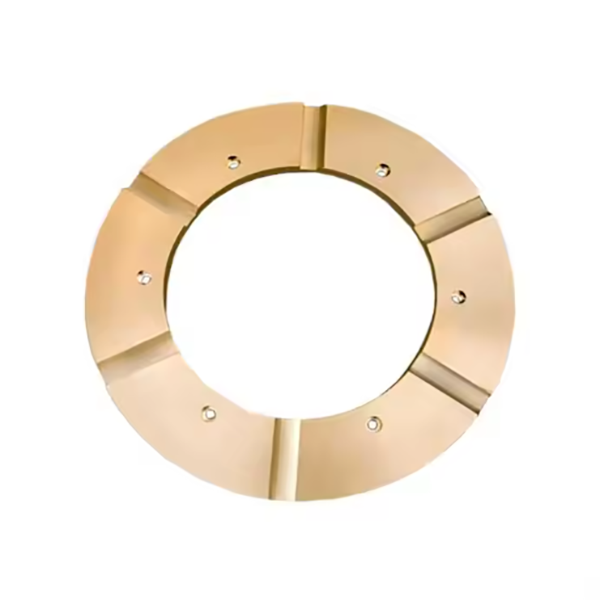
The socket liner is typically a cylindrical or flanged sleeve with precise internal and external dimensions, featuring the following key parts and structural details:
Liner Body: A hollow cylindrical sleeve made of bearing bronze (e.g., ZCuSn10Pb1), babbitt metal (tin-based: Sn 83–85%, Sb 11–13%), or steel-backed bimetallic material (steel shell with a sintered bronze layer). The wall thickness ranges from 5–15 mm, depending on the crusher size.
Inner Bearing Surface: A precision-machined surface with a low roughness (Ra0.8–1.6 μm) that directly contacts the main shaft. It often features circumferential oil grooves (0.5–2 mm deep) to retain lubricant and enhance friction reduction.
Outer Surface: A cylindrical or slightly tapered surface that fits into the socket’s bearing cavity with an interference fit (0.01–0.05 mm) to prevent rotation relative to the socket.
Flange (Optional): A radial flange at one end to limit axial movement in the socket, ensuring the liner remains seated under heavy axial loads.
Lubrication Features:
Oil Grooves: Axial or spiral grooves on the inner surface that distribute lubricant evenly along the contact area, preventing dry friction.
Oil Holes: Small holes (φ3–φ6 mm) connecting the outer surface to the inner grooves, aligning with the socket’s lubrication channels to ensure oil flow.
Chamfers: Rounded edges (0.5–2 mm radius) at both ends to facilitate installation and prevent stress concentration at the liner-shaft interface.
3. Manufacturing Process for the Socket Liner
Depending on the material, socket liners are produced using casting, sintering, or machining processes. For bronze liners, the primary process is:
Material Selection:
Bearing bronze (ZCuSn10Pb1) is preferred for its high compressive strength (≥300 MPa), good thermal conductivity, and compatibility with steel shafts. Its composition is controlled to Sn 9–11%, Pb 0.5–1.0%, Cu balance, with a hardness of HB 80–100.
Casting:
Centrifugal Casting: Molten bronze is poured into a rotating mold (1000–3000 rpm) to form a cylindrical sleeve with a dense, uniform structure. This method ensures concentricity and minimizes porosity (≤5% by volume).
Sand Casting: For flanged liners, sand molds are used with cores to form oil grooves or holes. Pouring temperature is 1000–1100°C to ensure complete filling of thin sections.
Heat Treatment:
Bronze liners undergo annealing at 500–600°C for 1–2 hours, followed by slow cooling, to relieve casting stress and improve machinability.
Machining and Finishing:
Rough Machining: The cast blank is turned on a lathe to machine outer diameter, inner bore, and flange (if applicable), leaving 0.5–1 mm finishing allowance.
Finish Machining: Inner and outer surfaces are precision-turned to achieve dimensional tolerances (IT6–IT7) and surface roughness Ra0.8 μm. The inner bore is honed for superior roundness (≤0.005 mm).
Oil Groove Machining: Grooves are milled or broached into the inner surface with precise depth and spacing to optimize lubricant retention.
4. Manufacturing Process for Bimetallic Liners
For high-load applications, steel-backed bimetallic liners are produced using:
Steel Shell Preparation: A low-carbon steel (Q235) sleeve is drawn or machined to the desired outer dimensions, then cleaned and roughened (e.g., via sandblasting) to enhance bonding with the bearing layer.
Bearing Layer Application:
Sintering: A bronze powder (e.g., CuSn10) is sintered onto the steel shell at 800–900°C in a protective atmosphere (nitrogen), forming a 0.5–2 mm thick porous layer.
Roll Bonding: A thin bronze sheet (0.3–1 mm thick) is cold-rolled onto the steel shell under high pressure (100–200 MPa), creating a metallurgical bond.
Final Machining: The inner surface is finish-machined to the required dimensions and roughness, with oil grooves added as needed.
5. Quality Control Processes
Material Testing:
Chemical composition analysis (spectrometry) verifies compliance with material standards (e.g., ZCuSn10Pb1: Sn 9–11%, Pb 0.5–1.0%).
Hardness testing (Brinell) ensures bronze liners have a hardness of HB 70–90, balancing wear resistance and ductility.
Dimensional Accuracy Checks:
A coordinate measuring machine (CMM) inspects inner/outer diameters, wall thickness uniformity, and flange thickness, with tolerances controlled to ±0.01 mm for critical dimensions.
Roundness and cylindricity of the inner surface are measured using a roundness tester, ensuring values ≤0.005 mm to prevent uneven wear.
Microstructural Analysis:
Metallographic examination checks for porosity (≤5% in bronze) and bonding quality in bimetallic liners (no delamination between steel and bearing layers).
Performance Testing:
Friction Coefficient Testing: A tribometer measures friction under simulated load (10–50 MPa) and speed (500–1500 rpm), requiring values ≤0.15 with lubrication.
Wear Testing: A pin-on-disk test subjects the liner material to 10⁶ cycles, with weight loss limited to ≤5 mg to ensure long service life.
Fit and Assembly Checks:
The liner is trial-fitted into a test socket to verify the interference fit: it should require light press force (5–20 kN) without distortion.
The inner bore is checked for compatibility with a standard main shaft sample, ensuring smooth rotation without binding under load.
Through these manufacturing and quality control processes, the socket liner achieves the precision, wear resistance, and low friction required to protect the socket and main shaft, ensuring efficient and reliable operation of cone crushers in mining and aggregate processing application