The cone crusher step plate (main shaft step plate) is a key load-bearing and structural component, primarily responsible for axial load transmission (handling several tons in medium-sized crushers), positioning/guiding the main shaft and moving cone, and providing mechanical support to reduce vibration.
Structurally, it is a disc-shaped part made of high-strength alloy steel (40CrNiMoA/35CrMo) with a 30–80 mm thickness. It features a central hole (±0.05 mm tolerance) for main shaft fit, step features (10–30 mm height, 20–50 mm width) interacting with thrust bearings, and 8–24 mounting holes for high-strength bolts (grade 8.8+).
Manufacturing involves:
Casting: Alloy steel melting (1500–1550°C), sand mold casting, followed by normalization (850–900°C) and quenching-tempering (820–860°C quenching, 500–600°C tempering).
Machining: Rough turning (2–3 mm allowance), precision grinding (Ra0.8–1.6 μm surface finish, ±0.02 mm dimensional tolerance), and drilling/tapping (±0.1 mm positional tolerance for holes).
Surface treatment: Shot-blasting and anti-rust coating (80–120 μm).
Quality control includes material testing (chemical composition, tensile strength ≥980 MPa for 40CrNiMoA), dimensional inspection (CMM and gauges), NDT (ultrasonic/magnetic particle testing for defects), and assembly/performance validation to ensure fit and stability
Detailed Introduction to the Cone Crusher Step Plate Component
1. Function and Role of the Step Plate
The cone crusher step plate, also known as the main shaft step plate, is an important structural and load - bearing component within the cone crusher. Its primary functions include:
Axial Load Transmission: It is responsible for transmitting the axial loads generated during the crushing process. When the moving cone of the cone crusher crushes materials, significant axial forces are produced. The step plate effectively transfers these forces to the main shaft and related supporting structures, ensuring the stable operation of the crusher. For example, in a medium - sized cone crusher, the axial load during normal operation can reach several tons, and the step plate plays a crucial role in bearing and transmitting this load.
Positioning and Guidance: It provides accurate positioning for the main shaft and moving cone assembly. By precisely fitting with other components, it ensures that the moving cone moves in a specific trajectory during operation. This is essential for maintaining the consistency of the crushing chamber size and the quality of the crushed products. Deviations in the position of the step plate can lead to uneven wear of the moving cone and fixed cone liners and affect the particle size distribution of the crushed materials.
Mechanical Support: The step plate offers mechanical support to the main shaft, helping to reduce vibration and shock during the crusher's operation. In a vibrating environment, it stabilizes the main shaft, which is beneficial for prolonging the service life of the main shaft and other related components such as bearings.
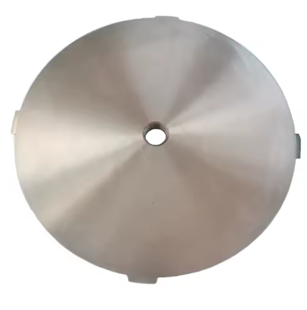
2. Composition and Structure of the Step Plate
The step plate is typically a circular - shaped or disc - like component with specific geometric features and structural details:
Plate Body: Usually made of high - strength alloy steel, such as 40CrNiMoA or 35CrMo. The material selection is based on its high tensile strength (for 40CrNiMoA, tensile strength ≥ 980 MPa), good impact toughness, and fatigue resistance. The plate has a thickness ranging from 30 mm to 80 mm, depending on the size and load requirements of the cone crusher. For large - scale crushers used in mining applications, a thicker step plate is required to withstand higher loads.
Central Hole: There is a precisely machined central hole in the step plate, which is used to fit over the main shaft. The diameter tolerance of this hole is strictly controlled, usually within ±0.05 mm, to ensure a tight and accurate fit with the main shaft. This fit is crucial for transmitting torque and axial loads effectively.
Step Feature: As the name implies, the step plate has one or more step - like structures on its surface. These steps are designed to interact with other components, such as thrust bearings or spacers. The height and width of the steps are carefully designed according to the mechanical requirements of the crusher. For example, the step height may range from 10 mm to 30 mm, and the width from 20 mm to 50 mm.
Mounting Holes: Distributed evenly around the circumference of the step plate are a number of mounting holes. These holes are used to fasten the step plate to other components, such as the moving cone or the supporting frame, using high - strength bolts (usually of grade 8.8 or higher). The number of mounting holes can vary from 8 to 24, depending on the size and design of the step plate.
3. Casting Process for the Step Plate
Material Preparation
The selected alloy steel, such as 40CrNiMoA, is first melted in an induction furnace. The melting temperature is carefully controlled within the range of 1500 - 1550 °C to ensure complete melting and uniform composition. During the melting process, alloying elements are added according to the predetermined chemical composition to adjust the properties of the steel.
Mold Making
For the step plate, a sand mold is commonly used. The sand mold is made by mixing silica sand, binder (such as resin), and other additives. A pattern is used to shape the sand mold, which is an exact replica of the step plate with allowances for shrinkage during cooling. The pattern is usually made of wood or metal. After the sand is packed around the pattern, it is compacted to ensure the integrity of the mold cavity.
Pouring
Once the mold is ready and the steel is melted to the appropriate temperature, the molten steel is poured into the mold cavity. The pouring speed is carefully controlled to avoid turbulence, which could introduce defects such as porosity or inclusions. The pouring is usually done under a certain pressure (if using a pressurized pouring system) to ensure that the molten steel fills every part of the mold cavity, especially in areas with complex geometries like the step features.
Cooling and Solidification
After pouring, the mold is allowed to cool slowly in a controlled environment. The cooling rate is crucial as it affects the microstructure and mechanical properties of the cast step plate. Generally, the cooling rate is controlled to be relatively slow to promote the formation of a fine - grained microstructure. This may involve covering the mold with insulation materials or placing it in a cooling chamber with a regulated temperature. The step plate is left in the mold until it has completely solidified, which may take several hours depending on its size.
Heat Treatment
Normalization: After being removed from the mold, the step plate is first normalized. It is heated to a temperature of around 850 - 900 °C and then air - cooled. Normalization helps to refine the grain structure, improve the mechanical properties, and relieve internal stresses.
Quenching and Tempering: Subsequently, the step plate undergoes quenching and tempering. It is heated to a quenching temperature (for 40CrNiMoA, around 820 - 860 °C), then rapidly cooled in oil. After quenching, it is tempered at a temperature of 500 - 600 °C for a certain period (usually 2 - 4 hours). This heat treatment process significantly improves the strength, toughness, and hardness of the step plate, making it suitable for the harsh working conditions of a cone crusher.
4. Machining and Manufacturing Process
Rough Machining
Turning: The cast step plate is first mounted on a lathe. The outer diameter and the central hole are rough - turned to remove excess material. The turning process reduces the diameter of the outer circle and the inner hole to a size close to the final dimensions, leaving a machining allowance of about 2 - 3 mm for subsequent precision machining.
Facing: The two flat surfaces of the step plate are faced to ensure their flatness. Facing is carried out using a cutting tool on the lathe, and the flatness tolerance at this stage is controlled within ±0.1 mm.
Precision Machining
Grinding: The outer diameter, central hole, and step surfaces are ground. The grinding process can achieve a high - precision surface finish. For example, the surface roughness of the ground surfaces can reach Ra0.8 - 1.6 μm. The dimensional tolerance of the outer diameter and central hole is further reduced to within ±0.02 mm, and the step height and width are machined to their exact design dimensions with a tolerance of ±0.05 mm.
Drilling and Tapping: The mounting holes are drilled and tapped. High - precision drilling machines are used to ensure the accurate position of the holes. The positional tolerance of the mounting holes is controlled within ±0.1 mm. After drilling, tapping is carried out to create internal threads for installing bolts. The thread tolerance follows the relevant national standards, such as 6H for internal threads.
Surface Treatment
The step plate may undergo surface treatment such as shot - blasting to remove surface impurities and improve the surface finish. After shot - blasting, it can be coated with an anti - rust paint or a corrosion - resistant coating. The anti - rust paint is usually applied in multiple layers, with a total thickness of about 80 - 120 μm, to protect the step plate from corrosion in harsh working environments, especially in mines where there may be moisture and corrosive substances.
5. Quality Control Processes
Material Testing
Chemical Composition Analysis: A spectrometer is used to analyze the chemical composition of the step plate material. The analysis ensures that the alloying elements in the steel, such as carbon, chromium, nickel, and molybdenum, are within the specified ranges. For 40CrNiMoA, the carbon content should be in the range of 0.37 - 0.44%, chromium 0.6 - 0.9%, nickel 1.2 - 1.6%, and molybdenum 0.15 - 0.25%. Any deviation from these ranges may affect the mechanical properties of the step plate.
Mechanical Property Testing: Tensile tests are conducted on sample specimens taken from the step plate. The tensile strength, yield strength, and elongation are measured. For 40CrNiMoA step plates, the tensile strength should be ≥ 980 MPa, the yield strength ≥ 835 MPa, and the elongation ≥ 12%. Impact tests are also carried out to evaluate the impact toughness of the material, with a required impact energy of ≥ 60 J/cm².
Dimensional Inspection
Coordinate Measuring Machine (CMM): A CMM is used to measure the dimensions of the step plate, including the outer diameter, central hole diameter, step height, width, and the position of the mounting holes. The CMM can provide highly accurate measurements, and any dimensional deviation beyond the specified tolerances (such as outer diameter tolerance of ±0.02 mm, step height tolerance of ±0.05 mm) will result in the rejection of the step plate.
Gauge Inspection: Special gauges are used to check the fit of the central hole and the step features. For example, a ring gauge is used to check the diameter of the central hole, and a step gauge is used to verify the step height and width. The gauges are calibrated regularly to ensure accurate inspection results.
Non - Destructive Testing (NDT)
Ultrasonic Testing (UT): UT is used to detect internal defects in the step plate, such as cracks, porosity, or inclusions. Ultrasonic waves are transmitted through the step plate, and any defects will cause reflections that can be detected by the ultrasonic equipment. Defects larger than a certain size (usually defined as a crack length of ≥ 2 mm or a porosity diameter of ≥ 1 mm) are not acceptable.
Magnetic Particle Testing (MPT): MPT is mainly used to detect surface and near - surface defects in ferromagnetic materials like the alloy steel of the step plate. A magnetic field is applied to the step plate, and magnetic particles are spread on the surface. Any defects will cause the magnetic particles to accumulate, indicating the presence and location of the defect. Surface cracks longer than 0.5 mm are considered unacceptable.
Assembly and Performance Testing
Assembly Verification: The step plate is assembled with other components of the cone crusher, such as the main shaft and moving cone, in a test setup. The assembly is checked to ensure a proper fit and alignment. For example, the step plate should fit smoothly onto the main shaft without any binding, and the mounting bolts should be able to be tightened to the specified torque without any problems.
Performance Simulation: The assembled cone crusher components with the step plate are subjected to performance simulation tests. These tests may include running the crusher at a low - load condition for a certain period to check for abnormal vibrations, noises, or excessive wear. If any performance issues are detected during the simulation tests, the step plate may need to be re - evaluated or replaced