The cone crusher lower frame, a foundational structural component, supports the entire assembly, distributes loads to the foundation, houses critical parts (thrust bearing, main shaft socket), and protects against contamination. It demands high rigidity and strength.
Structurally, it includes a cast steel/ductile iron body (500kg–5 tons) with reinforcing ribs, thrust bearing seat, main shaft socket mount, lubrication/cooling channels, foundation flange, access ports, and sealing surfaces.
Manufacturing involves sand casting (material selection, pattern making, molding, melting/pouring) with heat treatment, followed by machining (rough and precision) and surface treatment.
Quality control covers material testing, dimensional checks (CMM, laser scanning), structural integrity testing (UT, MPT), mechanical performance tests, and assembly validation, ensuring it meets strength and precision requirements for reliable heavy-duty operation.
Detailed Introduction to the Cone Crusher Lower Frame Component
1. Function and Role of the Lower Frame
The cone crusher lower frame (also known as the base frame or bottom frame) serves as the foundational structural component that supports the entire crusher assembly. Its primary functions include:
Structural Support: Bearing the weight of all upper components, including the main frame, eccentric bushing, moving cone, and concave, as well as the dynamic loads generated during crushing (up to tens of thousands of kilonewtons).
Load Distribution: Transmitting static and dynamic loads to the crusher’s foundation, ensuring stable operation and preventing excessive vibration.
Component Housing: Enclosing and positioning critical parts such as the thrust bearing, main shaft socket, and lubrication system, maintaining their alignment and functionality.
Contamination Protection: Acting as a barrier to prevent dust, ore particles, and moisture from entering internal components, reducing wear and extending service life.
As a heavy-duty structural part, the lower frame requires high rigidity, tensile strength, and impact resistance to withstand harsh operating conditions in mining and aggregate processing.
2. Composition and Structure of the Lower Frame
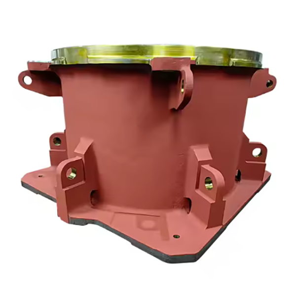
The lower frame is a large, robust casting with a complex geometry, featuring the following key components and structural details:
Frame Body: A one-piece cast steel or ductile iron structure with a cylindrical or conical outer profile, typically weighing 500 kg to 5 tons depending on the crusher size. Its wall thickness ranges from 20–50 mm, with reinforced ribs in high-stress areas.
Thrust Bearing Seat: A machined recess or flange at the top of the frame that houses the thrust bearing, with precise flatness (≤0.05 mm/m) to ensure proper load distribution.
Main Shaft Socket Mount: A central bore or cylindrical cavity that secures the main shaft socket, with dimensional tolerance IT7 to maintain concentricity with the main shaft.
Reinforcing Ribs: Internal or external radial/axial ribs that enhance rigidity without excessive weight, positioned to resist bending and torsional stress.
Lubrication and Cooling Channels: Drilled or cast passages that connect to the lubrication system, delivering oil to the thrust bearing and main shaft socket, and in some designs, cooling water channels to dissipate heat.
Foundation Mounting Flange: A radial flange at the base with bolt holes (typically 8–24 holes) for securing the frame to the concrete foundation. The flange has flatness tolerance ≤0.1 mm/m to ensure even load distribution.
Access Doors/Inspection Ports: Removable panels or covers that allow maintenance access to internal components (e.g., thrust bearing, lubrication lines) without disassembling the entire frame.
Sealing Surfaces: Machined surfaces that interface with the upper frame or adjustment ring, fitted with gaskets or O-rings to prevent material leakage and contamination.
3. Casting Process for the Lower Frame
Given its large size and complex structure, the lower frame is primarily manufactured using sand casting with cast steel or ductile iron:
Material Selection:
Cast Steel (ZG270-500): Preferred for large crushers due to its high tensile strength (≥500 MPa), yield strength (≥270 MPa), and impact toughness (≥20 J/cm²). Chemical composition: C 0.24–0.32%, Si 0.20–0.60%, Mn 0.50–0.80%.
Ductile Iron (QT500-7): Used for medium-sized crushers, offering good castability and vibration damping. Tensile strength ≥500 MPa, elongation ≥7%.
Pattern Making:
A full-scale pattern is created using 3D-printed resin, wood, or foam, replicating the frame’s outer profile, ribs, mounting flange, and internal cavities. Shrinkage allowances (1.5–2.5%) are added to account for cooling contraction.
Molding:
A resin-bonded sand mold is prepared with multiple sections to accommodate the frame’s complexity. Sand cores (bonded with phenolic resin) form internal features like ribs, channels, and bores. The mold is coated with a refractory wash to improve surface finish.
Melting and Pouring:
For cast steel: Melted in an electric arc furnace at 1520–1560°C, with strict control of sulfur (≤0.04%) and phosphorus (≤0.04%) to avoid brittleness.
For ductile iron: Melted in a cupola or induction furnace at 1400–1450°C, with nodulizers (magnesium or cerium) added to convert graphite to spherical form.
Pouring is performed via a ladle with a controlled flow rate (100–300 kg/s) to ensure complete mold filling, minimizing porosity and cold shuts.
Heat Treatment:
Cast Steel: Normalized at 850–900°C for 4–6 hours, then air-cooled to refine grain structure and reduce internal stress.
Ductile Iron: Annealed at 850–900°C for 2–4 hours to eliminate carbides, followed by slow cooling to enhance machinability.
4. Machining and Manufacturing Process
Rough Machining:
The cast frame is mounted on a CNC gantry mill or vertical lathe to machine the foundation flange, outer surfaces, and access port edges, leaving 5–10 mm finishing allowance. Key dimensions (e.g., flange diameter) are controlled to ±1 mm.
Precision Machining of Critical Features:
Thrust Bearing Seat: Finish-machined using a CNC grinder to achieve flatness (≤0.05 mm/m) and surface roughness Ra1.6 μm, ensuring proper thrust bearing seating.
Main Shaft Socket Mount: Bored and honed to dimensional tolerance IT7 (e.g., φ300H7) and cylindricity ≤0.02 mm, maintaining concentricity with the thrust bearing seat (coaxiality ≤0.1 mm).
Foundation Flange: Machined to flatness (≤0.1 mm/m) and perpendicularity to the frame axis (≤0.2 mm/100 mm) using a CNC milling machine. Bolt holes are drilled and tapped to class 6H tolerance, with positional accuracy (±0.5 mm).
Channel and Port Machining:
Lubrication and cooling channels are drilled using CNC deep-hole drilling machines, with diameter tolerance (±0.5 mm) and positional accuracy (±1 mm) to ensure alignment with connected components.
Inspection ports and access doors are machined to ensure proper fit with gaskets, preventing leakage.
Surface Treatment:
Machined surfaces (e.g., thrust bearing seat, socket mount) are polished to Ra1.6 μm to reduce friction and improve component mating.
Exterior surfaces are blast-cleaned and painted with epoxy primer (80–100 μm) and topcoat (60–80 μm) to resist corrosion in outdoor or dusty environments.
5. Quality Control Processes
Material Testing:
Chemical composition analysis (spectrometry) verifies compliance with cast steel (ZG270-500) or ductile iron (QT500-7) standards.
A coordinate measuring machine (CMM) inspects critical dimensions: thrust bearing seat flatness, socket mount diameter, and flange bolt hole positions.
Laser scanning verifies the overall geometry matches the CAD model, ensuring compatibility with upper components.
Structural Integrity Testing:
Ultrasonic testing (UT) detects internal defects (e.g., shrinkage pores, cracks) in high-stress areas like ribs and flanges, with defects >φ5 mm rejected.
Magnetic particle testing (MPT) checks for surface cracks in machined features (e.g., bolt holes, bearing seat edges), with linear defects >2 mm resulting in rejection.
Mechanical Performance Testing:
Pressure testing of cooling/lubrication channels (at 1.5× operating pressure) ensures no leaks.
Load testing involves applying simulated static loads (120% of rated weight) to the frame, with deformation measured via strain gauges (limit: ≤0.1 mm/m).
Assembly Validation:
Trial assembly with the thrust bearing, main shaft socket, and foundation bolts verifies proper fit: components seat securely without binding, and alignment tolerances are maintained.
Through these manufacturing and quality control processes, the lower frame achieves the structural integrity, precision, and durability required to support the cone crusher’s operation, ensuring reliable performance in heavy-duty industrial applications.