The cone crusher counterweight guard, a protective and structural component surrounding the counterweight and eccentric bushing, functions as a safety barrier against rotating parts (500–1500 rpm), blocks contaminants, reinforces stability, and reduces noise.
Structurally, it consists of a 4–8 mm thick annular body (Q235/Q355B steel or HT250 cast iron), mounting flanges with bolt holes, 1–2 access doors, reinforcement ribs, ventilation slots, lifting lugs, and an 80–120 μm corrosion-resistant coating.
Manufactured via steel plate welding (plasma cutting, rolling, MIG welding) or sand casting (1380–1420°C pouring) with annealing, it undergoes CNC machining for flange flatness (≤0.5 mm/m) and surface finishing. Quality control includes material testing, weld inspection (DPT), impact testing, dust tightness checks (0.1 MPa pressure), and safety validation (ISO 13857 compliance).
This ensures reliable protection and durability in mining/aggregate operations
Detailed Introduction to the Cone Crusher Counterweight Guard Component
1. Function and Role of the Counterweight Guard
The cone crusher counterweight guard (also called the balance weight shield or eccentric guard) is a protective and structural component installed around the counterweight and eccentric bushing assembly. Its primary functions include:
Safety Protection: Acting as a physical barrier to prevent operators, tools, or debris from contacting the rotating counterweight and eccentric bushing (operating at 500–1500 rpm), reducing the risk of entanglement or impact injuries.
Contamination Prevention: Blocking dust, ore particles, and moisture from entering the counterweight’s moving parts, such as bolts and mounting interfaces, minimizing wear and corrosion.
Structural Support: Reinforcing the counterweight assembly by limiting radial movement during operation, enhancing stability and reducing vibration transmitted to the frame.
Noise Reduction: Dampening mechanical noise generated by the rotating counterweight and eccentric bushing, contributing to a quieter working environment.
Operating in a dusty, high-vibration environment, the counterweight guard requires impact resistance, rigidity, and a secure mounting design to maintain its protective function over time.
2. Composition and Structure of the Counterweight Guard
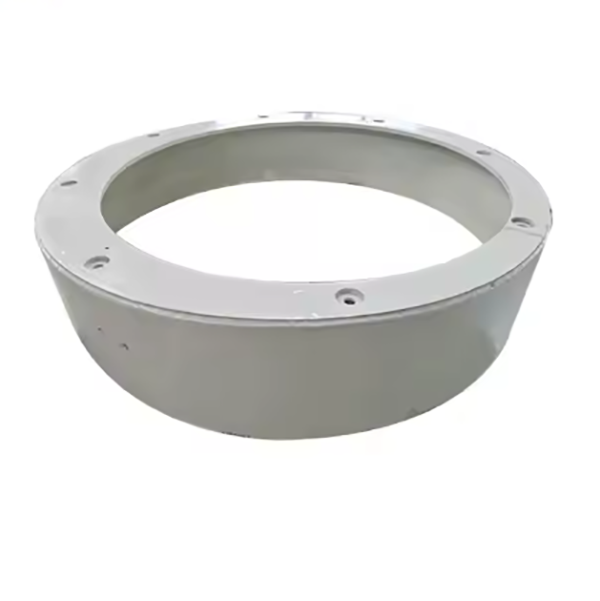
The counterweight guard is typically an annular or semi-annular shell with flanged edges, featuring the following key components and structural details:
Guard Body: A thin-walled (4–8 mm) cylindrical or conical structure made of mild steel (Q235), wear-resistant steel (Q355B), or cast iron (HT250). Its diameter ranges from 800 mm to 3000 mm, matching the counterweight’s outer dimensions.
Mounting Flanges: Radial flanges at the top and bottom edges, bolted to the upper frame and lower frame (or adjustment ring). These flanges have evenly spaced bolt holes (12–36) with positional tolerance (±1 mm) and are reinforced with gussets to resist vibration.
Access Doors: 1–2 hinged or bolted panels on the guard body, allowing inspection or maintenance of the counterweight without removing the entire guard. Doors are fitted with rubber gaskets to maintain dust tightness and latches for secure closure.
Reinforcement Ribs: Axial or circumferential ribs welded or cast onto the inner surface, spaced 200–500 mm apart, to enhance rigidity and prevent deformation under impact or vibration. Rib thickness ranges from 6–12 mm.
Ventilation Slots: Small, slotted openings (5–10 mm wide) with mesh screens to allow heat dissipation from the counterweight assembly while blocking debris. These are positioned to avoid direct line-of-sight to rotating parts.
Lifting Lugs: Welded or cast protrusions on the outer surface, designed to support the guard’s weight (50–300 kg) during installation and removal. Lugs are positioned symmetrically for balanced lifting.
Corrosion Protection: A painted or galvanized coating (80–120 μm thick) on all surfaces to resist rust in humid or outdoor environments.
3. Manufacturing Process for the Counterweight Guard
Depending on the material, the counterweight guard is produced using welding, casting, or a combination of both:
3.1 Steel Plate Welding (Most Common)
Material Selection: Mild steel (Q235) is used for general applications, while wear-resistant steel (Q355B) is chosen for high-impact environments. Both offer good weldability and cost-effectiveness.
Plate Cutting: Steel plates are cut to the guard body’s height and circumference using plasma cutting or laser cutting, with dimensional tolerance (±2 mm). Flange blanks are cut separately from thicker plates (8–12 mm).
Forming and Rolling: The body plate is rolled into a cylindrical or conical shape using a plate rolling machine, with the longitudinal seam welded via MIG (metal inert gas) welding. Welds are ground smooth to remove spatter and ensure a uniform surface.
Flange and Rib Installation: Mounting flanges are welded to the top and bottom edges of the body, with fillet welds (6–8 mm leg length) for strength. Reinforcement ribs are welded to the inner surface, with intermittent welds to reduce distortion.
Door Assembly: Access door frames are cut, bent, and welded to the guard body. Hinges, latches, and gaskets are installed, and doors are fitted to ensure a tight seal.
3.2 Cast Iron Casting (Heavy-Duty Designs)
Material Selection: Cast iron (HT250) is used for large, one-piece guards, offering good vibration damping and rigidity. Tensile strength ≥250 MPa, hardness HB 180–230.
Sand Casting: A resin-bonded sand mold is created using a foam or wood pattern of the guard, including flanges, ribs, and door recesses. Molten iron (1380–1420°C) is poured into the mold, then cooled and shaken out.
Heat Treatment: Annealing at 550–600°C relieves casting stress, reducing the risk of cracking during machining or operation.
4. Machining and Finishing
Flange Machining: Mounting flanges are machined on a CNC milling machine to achieve flatness (≤0.5 mm/m) and ensure proper seating against the frame. Bolt holes are drilled and tapped (if required) with tolerance H12, and edges are deburred.
Door Fitting: Door edges are machined to ensure a tight fit with the frame, with hinges aligned to allow smooth opening/closing. Latches are adjusted to secure doors without gaps.
Surface Preparation: The guard is sandblasted to remove scale and contaminants, ensuring good paint adhesion. Welded areas are ground to a smooth finish (Ra6.3 μm) to prevent injury during handling.
Coating Application: A primer (epoxy or zinc-rich) is applied to a thickness of 40–60 μm, followed by a topcoat (polyurethane) of 40–60 μm, providing corrosion resistance and UV protection for outdoor use.
5. Quality Control Processes
Material Testing:
Chemical composition analysis (spectrometry) verifies steel or cast iron compliance (e.g., Q235: C ≤0.22%, Mn 0.3–0.65%).
Tensile testing on welded samples confirms weld strength (≥345 MPa for Q355B).
Dimensional Accuracy Checks:
A laser scanner or tape measure verifies the guard’s diameter, height, and flange dimensions, with tolerance (±5 mm) for large components.
A straightedge and feeler gauge check flange flatness, ensuring values ≤0.5 mm/m to prevent uneven loading on bolts.
Structural Integrity Testing:
Weld Inspection: Welds are inspected visually and via dye penetrant testing (DPT) to detect cracks, porosity, or incomplete fusion.
Impact Testing: A 10 kg steel ball is dropped from 1 m onto the guard surface, with no visible deformation or cracking required (for Q355B guards).
Functional Testing:
Dust Tightness: The guard is sealed with gaskets, and a pressure test (0.1 MPa) is performed; no air leakage through doors or seams is allowed.
Door Operation: Access doors are opened/closed 100 times to ensure hinges and latches function smoothly without binding.
Safety Validation:
A rotational safety test simulates contact with a 50 mm diameter probe, confirming the guard prevents access to rotating parts (compliance with ISO 13857).
Through these manufacturing and quality control processes, the counterweight guard provides reliable protection for operators and components, ensuring safe and efficient operation of the cone crusher in mining and aggregate processing applications