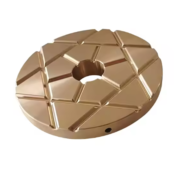
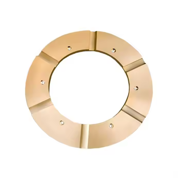
The cone crusher thrust bearing, a key component handling axial loads (up to thousands of kilonewtons) at the main shaft bottom or between the adjustment ring and frame, supports vertical forces, enables smooth rotation, maintains alignment, and integrates with lubrication systems. It operates at 500–1500 rpm, demanding high strength and precision. Composed of a 42CrMo thrust collar (HRC 50–55 surface), babbitt/bronze thrust pads, a cast iron/steel housing, lubrication elements, locating devices, and seals, it forms a robust assembly. Manufacturing involves forging and heat-treating the collar, casting/bonding babbitt to steel for pads, and sand-casting the housing, followed by precision machining. Assembly includes pad installation, lubrication integration, and alignment checks. Quality control covers material testing, dimensional inspection, NDT (UT, MPT), performance trials (load, friction), and lubrication validation. These ensure reliable operation in mining and aggregate processing.
The cone crusher socket liner, a replaceable wear-resistant component in the socket’s bearing cavity, acts as an interface between the rotating main shaft and stationary socket. It protects against wear, reduces friction (≤0.15 with lubrication), distributes loads, and compensates for minor misalignment, requiring good wear resistance and lubricant compatibility. Structurally, it is a cylindrical/flanged sleeve with a liner body (bronze, babbitt, or bimetallic materials), inner bearing surface (Ra0.8–1.6 μm with oil grooves), outer surface (interference fit), optional flange, lubrication features, and chamfers, with 5–15 mm wall thickness. Manufacturing involves casting (centrifugal/sand) for bronze liners, plus heat treatment and machining, or steel shell preparation, bearing layer application (sintering/roll bonding) and machining for bimetallic ones. Quality control includes material testing (composition, hardness), dimensional checks (CMM, roundness testing), microstructural analysis, performance tests (friction, wear), and fit checks, ensuring it protects components for efficient crusher operation
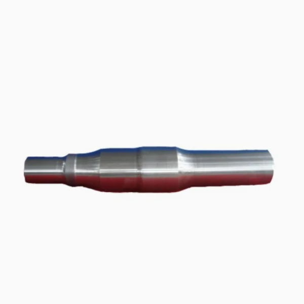
The cone crusher main shaft, a critical rotating component connecting the eccentric bushing to the moving cone, performs key functions such as power transmission (driving the moving cone's eccentric rotation), load bearing (withstanding axial and radial loads up to thousands of kilonewtons), eccentric motion guidance (maintaining the moving cone's orbital path), and structural alignment (ensuring concentricity between the moving and fixed cones). It requires exceptional tensile strength, fatigue resistance, and dimensional precision for operation at 500–1500 rpm. Structurally, it is a stepped, cylindrical or conical forged component consisting of the shaft body (high-strength alloy steel 42CrMo or 35CrNiMo with 100–500 mm diameter and 500–2000 mm length), upper cone mount, eccentric bushing interface, bearing journals, shoulders and keyways, and lubrication channels. The manufacturing process involves forging (billet heating to 1100–1200°C, open-die forging, precision forging) and heat treatment (quenching and tempering, local surface hardening). Its machining and manufacturing process includes rough machining, precision machining of critical features, lubrication channel drilling, balancing, and surface treatment. Quality control processes cover material and forging testing (chemical composition analysis, ultrasonic testing), dimensional accuracy checks (using CMM and laser alignment tool), mechanical property testing (hardness and tensile testing), non-destructive testing (MPT and eddy current testing), and functional testing (rotational and load testing). These processes ensure the main shaft achieves the required precision, strength, and reliability to drive the cone crusher's crushing motion in mining and aggregate processing applications