The cone crusher bowl, also known as the fixed cone housing or concave frame, is a key structural component forming the stationary outer shell of the crushing chamber. Positioned above the eccentric bushing and surrounding the mantle, its main functions include providing structural support for the bowl liner, forming the crushing chamber with the mantle, distributing loads to the base frame, and containing materials to ensure efficient flow. It requires high mechanical strength, rigidity, and dimensional accuracy, typically made of high-strength cast steel or welded steel plates.
Structurally, it is a large conical or cylindrical-frustoconical component with a hollow interior, consisting of the bowl body (high-strength cast steel like ZG35CrMo), bowl liner mounting interface (dovetail grooves, clamping flange), adjustment mechanism interface (threaded outer surface, guide slots), reinforcing ribs, discharge opening, and lubrication/inspection ports.
The casting process for the bowl involves material selection (ZG35CrMo), pattern making (with shrinkage allowances), molding (resin-bonded sand mold), melting and pouring (controlled temperature and flow rate), and cooling with heat treatment (normalization and tempering). Its machining process includes rough machining, thread and guide feature machining, inner surface and mounting interface machining, flange and bolt hole machining, and surface treatment.
Quality control processes cover material testing (chemical composition and tensile strength), dimensional accuracy checks (CMM and laser scanner), structural integrity testing (ultrasonic and magnetic particle testing), mechanical performance testing (hardness and load testing), and assembly/functional testing. These ensure the bowl has the required structural strength, precision, and reliability to withstand extreme crushing forces, enabling efficient long-term operation in mining and aggregate processing.
Detailed Introduction to the Cone Crusher Bowl Component
1. Function and Role of the Bowl
The cone crusher bowl (also referred to as the fixed cone housing or concave frame) is a key structural component that forms the stationary outer shell of the crushing chamber. Positioned above the eccentric bushing and surrounding the mantle, its primary functions include:
Structural Support: Housing and securing the bowl liner (fixed cone liner), providing a stable framework to withstand the high crushing forces (up to thousands of kilonewtons) generated during operation.
Crushing Chamber Formation: Working in conjunction with the mantle to form the annular crushing cavity, where material is compressed and fractured between the stationary bowl liner and rotating mantle.
Load Distribution: Transmitting axial and radial loads from the crushing process to the crusher’s base frame, reducing stress concentration on critical components like the main shaft and bearings.
Material Containment: Preventing crushed material from spilling out of the crushing chamber, ensuring efficient material flow through the discharge opening.
Given its role in heavy-load bearing and structural stability, the bowl requires high mechanical strength, rigidity, and dimensional accuracy, often made from high-strength cast steel or welded steel plates.
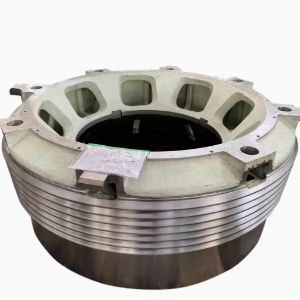
2. Composition and Structure of the Bowl
The bowl is typically a large, conical or cylindrical- frustoconical component with a hollow interior, consisting of the following key parts and structural details:
Bowl Body: The main structural shell, with a wall thickness of 80–200 mm, made from cast steel (e.g., ZG35CrMo) or welded low-alloy steel (e.g., Q355B). Its outer surface may feature reinforcing ribs, while the inner surface is machined to accommodate the bowl liner.
Bowl Liner Mounting Interface:
Dovetail Grooves: Longitudinal or circumferential grooves on the inner surface that mate with corresponding protrusions on the bowl liner, securing it against rotational forces during crushing.
Clamping Flange: A radial flange at the top of the bowl with bolt holes to fasten the bowl liner, ensuring it remains seated under impact loads.
Adjustment Mechanism Interface:
Threaded Outer Surface: Many bowls feature external trapezoidal threads that engage with the adjustment ring, allowing vertical adjustment of the bowl to modify the crushing gap (and thus the product size).
Guide Slots: Linear grooves on the outer surface that align with guide pins on the upper frame, preventing rotation of the bowl during gap adjustment.
Reinforcing Ribs: Radial or axial ribs (20–50 mm thick) distributed on the outer surface to enhance rigidity, reducing deflection under load to ≤0.5 mm at maximum operating pressure.
Discharge Opening: A circular or rectangular outlet at the bottom of the bowl, sized to control the maximum product size and facilitate material flow to the discharge conveyor.
Lubrication and Inspection Ports: Small openings or channels for lubricant delivery to the adjustment thread interface and for visual inspection of the bowl liner’s wear status.
3. Casting Process for the Bowl
For large and complex bowl designs, sand casting is the primary manufacturing method, ensuring structural integrity and dimensional precision:
Material Selection:
High-strength cast steel (ZG35CrMo) is preferred for its excellent tensile strength (≥700 MPa), impact toughness (≥35 J/cm²), and weldability, making it suitable for heavy-load applications.
Pattern Making:
A full-scale pattern is created using polyurethane foam or wood, replicating the bowl’s outer shape, inner cavity, ribs, threads (simplified), and flange details. Shrinkage allowances (1.5–2.5%) are added, with larger allowances for thick-walled sections.
The pattern includes internal cores to form the hollow cavity and mounting grooves, ensuring accurate dimensional relationships between features.
Molding:
A resin-bonded sand mold is prepared, with the pattern positioned in the drag (lower mold half) and the cope (upper mold half) formed over it. Sand cores are inserted to create the inner cavity and ribs, with precise alignment to ensure wall thickness uniformity (tolerance ±3 mm).
Melting and Pouring:
The cast steel is melted in an electric arc furnace at 1520–1560°C, with chemical composition controlled to C 0.32–0.40%, Cr 0.8–1.1%, and Mo 0.15–0.25% to balance strength and toughness.
Pouring is performed using a bottom-pour ladle, with a controlled flow rate (50–100 kg/s) to fill the mold cavity without turbulence, minimizing porosity and ensuring complete filling of thin ribs.
Cooling and Heat Treatment:
The casting is cooled in the mold for 72–120 hours to reduce thermal stress, then removed via shakeout. Shot blasting (G18 steel grit) removes sand residues, achieving a surface roughness of Ra50–100 μm.
Normalization: Heating to 850–900°C for 4–6 hours, followed by air cooling to refine the grain structure.
Tempering: Heating to 600–650°C for 3–5 hours to reduce hardness to 180–230 HBW, improving machinability while maintaining strength.
4. Machining and Manufacturing Process
Rough Machining:
The cast bowl is mounted on a CNC vertical lathe to machine the outer surface, top flange, and bottom discharge opening, leaving 5–8 mm finishing allowance. Key dimensions (outer diameter, height) are controlled to ±1 mm.
Thread and Guide Feature Machining:
External trapezoidal threads (for adjustment) are rough-cut using a CNC thread milling machine, with a 0.5–1 mm finish allowance. Thread parameters (pitch, lead, profile) are checked to ensure compatibility with the adjustment ring.
Guide slots are milled into the outer surface using a CNC milling machine, with depth (10–20 mm) and width (15–30 mm) tolerances of ±0.1 mm to align with the upper frame’s guide pins.
Inner Surface and Mounting Interface Machining:
The inner surface (mating with the bowl liner) is finish-turned to achieve a surface roughness of Ra3.2 μm and a taper angle tolerance of ±0.1°, ensuring proper fit with the bowl liner.
Dovetail grooves are precision-machined into the inner surface using a CNC broaching machine, with dimensions (depth, width) controlled to ±0.05 mm for secure liner retention.
Flange and Bolt Hole Machining:
The top clamping flange is finish-machined to flatness (≤0.05 mm/m) and perpendicularity to the bowl axis (≤0.1 mm/100 mm) using a CNC grinder.
Bolt holes are drilled and tapped to class 6H tolerance, with positional accuracy (±0.2 mm) relative to the flange centerline to ensure uniform clamping force on the bowl liner.
Surface Treatment:
The outer surface is coated with an epoxy primer and polyurethane topcoat (total thickness 100–150 μm) to resist corrosion in harsh mining environments.
Threaded surfaces are treated with anti-seize compound to facilitate smooth adjustment and prevent galling.
5. Quality Control Processes
Material Testing:
Chemical composition analysis (via optical emission spectrometry) verifies the cast steel meets specifications (e.g., ZG35CrMo: C 0.32–0.40%, Cr 0.8–1.1%).
Tensile testing on cast samples confirms tensile strength ≥700 MPa and elongation ≥15%.
A laser scanner verifies the overall profile, ensuring compliance with the 3D CAD model.
Structural Integrity Testing:
Ultrasonic testing (UT) is performed on the bowl body and ribs to detect internal defects (e.g., shrinkage pores >φ5 mm are rejected).
Magnetic particle testing (MPT) checks for surface cracks in high-stress areas (thread roots, flange edges), with any linear defects >1 mm resulting in rejection.
Mechanical Performance Testing:
Hardness testing (Brinell) ensures the bowl has a hardness of 180–230 HBW, balancing strength and machinability.
Load testing involves applying 120% of the rated crushing force via hydraulic presses, with post-test inspection showing no permanent deformation (deflection ≤0.3 mm).
Assembly and Functional Testing:
A trial fit with the bowl liner and adjustment ring confirms proper alignment: the liner seats securely in the dovetail grooves, and the adjustment ring rotates smoothly without binding.
The discharge opening is measured to ensure it matches the design size (tolerance ±2 mm), verifying proper material flow.
Through these manufacturing and quality control processes, the cone crusher bowl achieves the structural strength, dimensional precision, and reliability required to withstand extreme crushing forces, ensuring efficient and long-term operation in mining, quarrying, and aggregate processing applications