This paper details the main shaft sleeve of cone crushers, a crucial component positioned between the main shaft and the eccentric assembly. It primarily functions in radial support, friction reduction, load distribution, and lubrication retention. The component consists of the sleeve body, inner bore, outer surface, lubrication channels, flange (in some designs), and wear indicator grooves, each with specific structural features. The casting process for the bronze sleeve body is elaborated, including material selection (phosphor bronze), pattern making, molding, melting, pouring, heat treatment, and inspection. The machining and manufacturing process is also described, covering rough/finish machining, surface treatment, and assembly preparation. Additionally, quality control measures are specified, such as material validation, dimensional accuracy checks, surface quality inspection, functional testing, and wear resistance testing. These processes ensure the main shaft sleeve provides reliable support and friction reduction, enhancing the cone crusher’s efficiency and service life under heavy loads.
Detailed Introduction to the Cone Crusher Main Shaft Sleeve Component
1. Function and Role of the Main Shaft Sleeve
The main shaft sleeve (also called the main shaft bushing) is a critical component in cone crushers, positioned between the main shaft and the eccentric assembly. Its primary functions include:
Radial Support: Stabilizing the main shaft during high-speed rotation, ensuring concentric alignment with the eccentric sleeve to prevent wobbling.
Friction Reduction: Acting as a wear-resistant interface between the rotating main shaft and stationary or semi-stationary components, minimizing metal-to-metal contact.
Load Distribution: Absorbing radial forces generated during crushing, protecting the main shaft from excessive stress and premature failure.
Lubrication Retention: Containing lubricants in the clearance between the sleeve and shaft, maintaining a hydrodynamic oil film for smooth operation.
2. Composition and Structure of the Main Shaft Sleeve
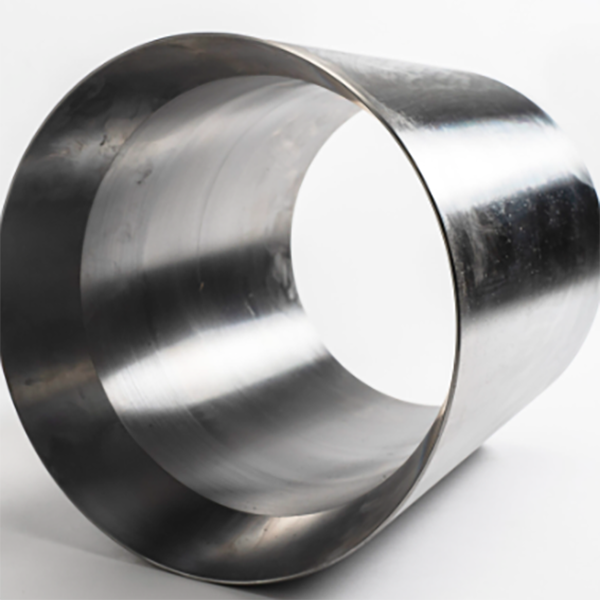
The main shaft sleeve is typically a cylindrical or tapered hollow component with precise internal and external dimensions, consisting of:
Sleeve Body: The core cylindrical structure, usually made of high-strength cast bronze (e.g., CuSn10Pb1) or alloy steel (42CrMo) with a wear-resistant surface. Its length and thickness vary by crusher model, matching the main shaft’s diameter and load requirements.
Inner Bore: A precision-machined central hole that fits over the main shaft with a controlled clearance (0.1–0.3 mm), allowing rotation while maintaining lubricant film. The bore may feature spiral grooves or oil pockets to enhance lubricant distribution.
Outer Surface: Machined to fit tightly into the eccentric sleeve or frame, often with a tapered profile (1:10 or 1:20) for interference fit, preventing relative movement under load.
Lubrication Channels: Axial or radial holes drilled through the sleeve to deliver oil from the main lubrication system to the inner bore, ensuring continuous lubrication at the shaft-sleeve interface.
Flange or Collar (in some designs): A radial projection at one end to axially locate the sleeve, preventing axial displacement during operation.
Wear Indicator Grooves: shallow circumferential grooves on the inner bore to visually indicate wear levels—when grooves are worn away, the sleeve requires replacement.
3. Casting Process for the Sleeve Body
For bronze sleeves (most common due to excellent anti-friction properties), the casting process is as follows:
Material Selection: Phosphor bronze (CuSn10Pb1) is preferred for its high wear resistance, good thermal conductivity, and compatibility with steel shafts. It contains 10% tin (Sn), 1% lead (Pb), and balance copper (Cu) for optimal machinability.
Pattern Making: A metal or wax pattern is created to replicate the sleeve’s geometry, including inner bore, outer surface, and lubrication channels. For investment casting (used for complex designs), wax patterns are assembled onto a sprue.
Molding:
For sand casting: Resin-bonded sand molds are formed around the pattern, with a core to shape the inner bore.
For investment casting: Wax patterns are coated with ceramic slurry, dried to form a shell, then melted out to leave a hollow ceramic mold.
Melting and Pouring: Bronze is melted in an induction furnace at 1080–1120°C. Molten metal is poured into the mold under gravity or pressure, ensuring complete filling of thin sections (e.g., flange edges).
Cooling and Shakeout: The casting cools to room temperature, then is removed from the mold. Sand castings undergo shot blasting to remove residual sand; investment castings have ceramic shells removed via vibration or water jet.
Heat Treatment: Bronze sleeves are annealed at 600–650°C for 1–2 hours, then air-cooled to relieve internal stress and improve machinability.
Casting Inspection: Visual checks for surface defects (porosity, cracks, or incomplete filling). Ultrasonic testing (UT) detects internal flaws, ensuring no defects larger than φ1 mm in critical load-bearing areas.
4. Machining and Manufacturing Process
Rough Machining:
The outer surface and flange (if present) are turned to remove excess material, leaving 0.5–1 mm finishing allowance.
The inner bore is rough-drilled and reamed to approximate size, with initial machining of lubrication channel holes.
Finish Machining:
Inner bore: Precision honed to achieve IT6 tolerance, with a surface roughness of Ra0.4–0.8 μm to reduce friction. Spiral grooves (if required) are cut using a CNC lathe with a grooving tool, with depth and pitch controlled to ±0.02 mm.
Outer surface: Ground to a tapered or cylindrical profile (depending on design) with IT7 tolerance, ensuring tight fit with the eccentric sleeve. Tapered surfaces are verified using a taper gauge.
Lubrication channels: Drilled and tapped to connect with the crusher’s lubrication system, with deburred edges to prevent oil flow obstruction.
Surface Treatment:
The inner bore may be coated with a solid lubricant (e.g., molybdenum disulfide) or electroplated with hard chrome (5–10 μm thick) to enhance wear resistance.
The outer surface is polished to remove burrs and ensure proper interference fit with mating components.
Assembly Preparation:
The sleeve is heated (200–300°C) to expand its outer diameter for press-fitting into the eccentric sleeve (shrink fit).
After cooling, the inner bore clearance with the main shaft is measured using feeler gauges to ensure it meets specifications (0.1–0.3 mm).
Roundness of the inner bore is measured with a roundness tester, requiring ≤0.005 mm deviation.
Surface Quality Inspection:
Inner bore surface roughness is checked with a profilometer, ensuring Ra ≤0.8 μm.
Visual and dye penetrant testing (DPT) detects cracks or scratches on critical surfaces.
Functional Testing:
Clearance verification: The sleeve is trial-fitted onto a test shaft to confirm radial clearance within the design range.
Lubrication flow test: Oil is pumped through channels to ensure unobstructed flow to the inner bore grooves.
Wear Resistance Testing:
A sample sleeve undergoes accelerated wear testing under simulated load and speed conditions, verifying wear rate ≤0.01 mm/100 hours.
The main shaft sleeve’s precise manufacturing and strict quality control ensure it provides reliable support and friction reduction, directly contributing to the cone crusher’s efficiency and service life under heavy crushing loads