This paper provides a detailed account of the cone crusher gear, a core transmission component that transfers motor power to the eccentric shaft, driving the moving cone's oscillation. It fulfills key roles in power transmission, speed regulation, and torque amplification, requiring high strength, wear resistance, and precision.
The gear's composition and structure are outlined, including the gear body (alloy steel, solid or hollow), teeth (involute profile with specific parameters), bore/shaft connection, hub/flange, lubrication grooves, and webs/ribs for large gears.
For large bull gears, the casting process is detailed: material selection (ZG42CrMo), pattern making, molding, melting, pouring, cooling, and heat treatment. The machining process covers rough machining, tooth cutting (hobbing or shaping), hardening heat treatment (carburizing, quenching, tempering), finish machining (grinding), and deburring.
Quality control measures include material testing (chemical analysis, tensile and impact tests), dimensional checks (CMM, gear measuring center), hardness and microstructure testing, dynamic performance testing (mesh and load tests), and non-destructive testing (MPT, UT). These ensure the gear meets precision, strength, and durability requirements, guaranteeing reliable operation in heavy-duty crushing scenarios.
Detailed Introduction to the Cone Crusher Gear Component
1. Function and Role of the Cone Crusher Gear
The cone crusher gear (often referred to as the drive gear or pinion gear) is a core transmission component that transfers power from the motor to the crusher’s eccentric shaft, driving the oscillating motion of the moving cone. Its primary functions include:
Power Transmission: Converting the motor’s rotational energy into mechanical motion via meshing with the eccentric gear or bull gear, enabling the crushing cycle.
Speed Regulation: Adjusting the rotational speed of the eccentric shaft (typically 150–300 rpm) to match the crusher’s design throughput and material hardness.
Torque Amplification: Increasing torque to overcome the high resistance encountered during material crushing, ensuring stable operation under heavy loads.
Given its role in high-torque, continuous operation, the gear must 具备 high strength, wear resistance, and precision to avoid premature failure.
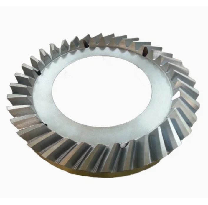
2. Composition and Structure of the Cone Crusher Gear
Cone crusher gears are typically cylindrical spur or bevel gears, with the following key components and structural features:
Gear Body: A cylindrical or conical structure made of high-strength alloy steel (e.g., 40CrNiMoA or 20CrMnTi),with external teeth machined to precise dimensions. The body may be solid (for small gears) or hollow (for large gears) to reduce weight while maintaining rigidity.
Teeth: The most critical part, with a involute profile (pressure angle 20°) to ensure smooth meshing. Tooth parameters include modulus (8–20), number of teeth (15–40), and face width (100–300 mm), tailored to the crusher’s power rating.
Bore or Shaft Connection: A central bore (for pinion gears) or keyway (for bull gears) that connects to the motor shaft or eccentric assembly. The bore is precision-machined to ensure concentricity with the gear teeth, minimizing vibration.
Hub or Flange: A reinforced section at the gear’s end, featuring bolt holes or splines to secure the gear to the shaft or coupling. The hub enhances torque transmission and prevents axial displacement.
Lubrication Grooves: Circumferential or axial grooves on the tooth flanks and bore surface to distribute lubricant, reducing friction and wear during meshing.
Webs or Ribs: Internal reinforcing structures in large gears (diameter >500 mm) to reduce weight and improve heat dissipation without compromising structural integrity.
3. Casting Process for the Gear (for Large Bull Gears)
Large gears (e.g., bull gears with diameter >800 mm) are often manufactured via casting to achieve complex shapes and high structural strength:
Material Selection:
High-strength cast steel (ZG42CrMo) is preferred for its excellent combination of tensile strength (≥785 MPa), impact toughness (≥45 J/cm²), and hardenability.
Pattern Making:
A full-scale foam or wood pattern is created, replicating the gear’s outer diameter, teeth, bore, and hub. Shrinkage allowances (2–3%) and draft angles (3°) are added to account for post-casting contraction.
Molding:
Resin-bonded sand molds are formed around the pattern, with a sand core used to create the central bore. The mold cavity is coated with a refractory wash to ensure a smooth surface finish.
Melting and Pouring:
The alloy steel is melted in an electric arc furnace at 1550–1600°C, with chemical composition controlled to C (0.40–0.45%), Cr (0.9–1.2%), and Mo (0.15–0.25%).
Pouring is performed at 1480–1520°C using a bottom-pouring ladle to minimize turbulence, ensuring uniform filling of the mold cavity.
Cooling and Shakeout:
The casting is cooled in the mold for 72–96 hours to reduce thermal stress, then removed via vibration. Sand residues are cleaned using shot blasting.
Heat Treatment:
Normalization (860–900°C, air-cooled) refines the grain structure, followed by tempering (600–650°C) to achieve a hardness of 220–250 HBW, improving machinability.
4. Machining and Manufacturing Process
Rough Machining:
The gear blank is mounted on a CNC lathe to turn the outer diameter, face, and bore, leaving 3–5 mm finishing allowance. Keyways or splines are rough-machined using a milling machine.
Tooth Cutting:
For spur gears: Teeth are cut using a gear hobbing machine (with a hob of matching modulus),achieving a rough profile with a 0.3–0.5 mm finishing allowance.
For bevel gears: A gear shaper or CNC bevel gear generator is used to cut the conical tooth profile, ensuring accurate meshing with the mating gear.
Heat Treatment for Hardening:
The gear undergoes carburizing (900–930°C for 8–12 hours) to create a hard surface layer (0.8–1.5 mm thick),followed by quenching (oil-cooled to 850–880°C) and low-temperature tempering (180–200°C). This results in a surface hardness of HRC 58–62 (for wear resistance) and a tough core (HRC 30–35).
Finish Machining:
Teeth are ground using a gear grinder to achieve AGMA 6–8 accuracy,with tooth profile deviations ≤0.02 mm and surface roughness Ra0.8–1.6 μm.
The bore and mounting surfaces are precision-ground to IT6 tolerance,ensuring concentricity with the gear axis (runout ≤0.03 mm).
Deburring and Polishing:
Tooth edges are deburred using a brush or abrasive wheel to prevent stress concentration and reduce noise during meshing.
Lubrication grooves are polished to ensure unobstructed oil flow.
5. Quality Control Processes
Material Testing:
Chemical composition analysis (via spectrometry) verifies alloy content (e.g., 40CrNiMoA: C 0.37–0.44%, Ni 1.25–1.65%).
Tensile testing on coupons confirms yield strength (≥835 MPa) and impact toughness (≥68 J/cm² at -20°C).
Dimensional Accuracy Checks:
A coordinate measuring machine (CMM) inspects key parameters: tooth pitch error (≤0.02 mm), tooth thickness (±0.015 mm), and bore concentricity.
A gear measuring center evaluates the involute profile, helix angle, and tooth spacing, ensuring compliance with AGMA standards.
Hardness and Microstructure Testing:
Surface hardness is measured using a Rockwell hardness tester (HRC 58–62 required for the tooth surface).
Metallographic analysis checks the carburized layer’s depth and microstructure (no excessive retained austenite or carbide networks).
Dynamic Performance Testing:
Gear mesh testing: The gear is paired with its mating gear on a test rig to measure noise (≤85 dB at rated speed) and vibration (≤0.1 mm/s).
Load testing: A 120% rated torque test is conducted for 2 hours to check for tooth deformation or cracking.
Non-Destructive Testing (NDT):
Magnetic particle testing (MPT) detects surface cracks in teeth and hub areas.
Ultrasonic testing (UT) inspects the gear body for internal defects (e.g., shrinkage pores >φ3 mm are rejected).
By adhering to these processes, the cone crusher gear achieves the required precision, strength, and durability, ensuring reliable power transmission and long service life in demanding crushing applications