The cone crusher eccentric bushing, a core rotating component around the main shaft, is crucial for driving the crushing motion. Its main functions are generating eccentric motion (converting rotational motion into orbital movement of the main shaft and moving cone), transmitting torque, bearing loads (up to thousands of kilonewtons), and serving as a lubrication channel.
Structurally, it is a cylindrical or conical sleeve with an offset inner bore, consisting of components such as the bushing body (high-strength alloy steel or cast steel like 42CrMo or ZG42CrMo), eccentric bore (with 5–20 mm offset), gear teeth (involute profile, modulus 10–25), lubrication passages, flange/shoulder, and wear-resistant liner (bronze or babbitt metal).
For large bushings (outer diameter >500 mm), the casting process involves material selection (ZG42CrMo), pattern making (with shrinkage allowances), molding (resin-bonded sand mold), melting and pouring (controlled temperature and flow rate), cooling and shakeout, and heat treatment (normalization and tempering). The machining process includes rough machining, gear machining, heat treatment for hardening (induction-hardened gear teeth to HRC 50–55), finish machining (grinding to AGMA 6–7 accuracy), installation of wear-resistant liner, and balancing.
Quality control covers material testing (chemical composition and mechanical properties), dimensional checks (CMM and laser tracker for eccentricity and concentricity), hardness and microstructure testing, non-destructive testing (UT and MPT), and performance testing (rotational and load tests). These ensure the eccentric bushing meets precision and durability requirements for efficient cone crusher operation in heavy-duty applications
Detailed Introduction to the Cone Crusher Eccentric Bushing Component
1. Function and Role of the Eccentric Bushing
The cone crusher eccentric bushing (also called the eccentric sleeve or eccentric cylinder) is a core rotating component located around the main shaft, playing a pivotal role in driving the crushing motion. Its primary functions include:
Eccentric Motion Generation: Converting the rotational motion of the drive gear into the eccentric (orbital) movement of the main shaft and moving cone, creating the crushing action by periodically closing and opening the gap between the moving and fixed cones.
Torque Transmission: Transferring torque from the pinion gear (via meshing with the eccentric gear) to the main shaft, ensuring sufficient force to crush hard materials like ores and rocks.
Load Bearing: Supporting the radial and axial loads generated during crushing (up to thousands of kilonewtons), distributing them evenly to the frame and bearings.
Lubrication Channel: Housing internal oil passages that deliver lubricant to the main shaft and bearings, reducing friction and heat buildup during high-speed rotation (typically 150–300 rpm).
Given its role in high-load, high-speed operation, the eccentric bushing must 具备 exceptional strength, wear resistance, and dimensional precision to avoid premature failure.
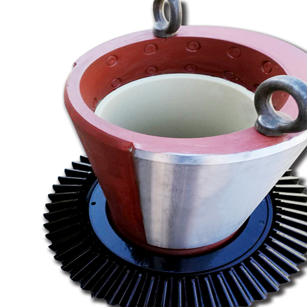
2. Composition and Structure of the Eccentric Bushing
The eccentric bushing is a cylindrical or conical sleeve with an offset inner bore, featuring the following key components and structural details:
Bushing Body: A thick-walled cylindrical structure made of high-strength alloy steel (e.g., 42CrMo or 35CrMo) or high-quality cast steel (ZG42CrMo). The outer surface is often equipped with a large gear (eccentric gear) that meshes with the pinion gear, with a modulus range of 10–25 and tooth count of 30–80.
Eccentric Bore: A central bore with an offset (eccentricity) relative to the outer diameter, typically 5–20 mm depending on the crusher model. This offset determines the stroke of the moving cone, directly affecting crushing efficiency and throughput.
Gear Teeth: Integrally formed or welded onto the outer surface of the bushing, with an involute profile (pressure angle 20°) to ensure smooth meshing with the pinion gear. The gear is designed for high torque transmission, with a face width of 150–400 mm.
Lubrication Passages: Internal drilled holes or grooves that connect to the main lubrication system, delivering oil to the interface between the bushing and main shaft, as well as to the upper and lower bearings.
Flange or Shoulder: A radial projection at one end of the bushing, acting as a thrust bearing surface to absorb axial loads and limit axial movement relative to the frame.
Wear-Resistant Liner: A replaceable inner sleeve made of bearing bronze (e.g., ZCuSn10Pb1) or babbitt metal, pressed into the inner bore to reduce friction between the bushing and main shaft.
The eccentricity (offset between inner and outer axes) is precisely controlled to ensure the moving cone’s stroke is consistent, directly influencing the crusher’s production capacity and product size.
3. Casting Process for the Eccentric Bushing
For large eccentric bushings (outer diameter >500 mm), casting is the preferred manufacturing method to achieve complex shapes and integral gear formation:
Material Selection:
High-strength cast steel (ZG42CrMo) is chosen for its excellent mechanical properties: tensile strength ≥800 MPa, yield strength ≥600 MPa, and impact toughness ≥45 J/cm². It offers good hardenability and wear resistance after heat treatment.
Pattern Making:
A full-scale pattern is created using wood, foam, or 3D-printed resin, replicating the bushing’s outer diameter, eccentric bore, gear teeth (simplified), flange, and lubrication passage positions. Shrinkage allowances (2–2.5%) are added, with larger allowances for the gear teeth and thick-walled sections.
The pattern includes cores to form the eccentric inner bore and oil passages, ensuring dimensional accuracy of the offset.
Molding:
A resin-bonded sand mold is prepared, with separate cores for the inner bore and gear teeth. The mold and cores are coated with a refractory wash (alumina-based) to prevent metal penetration and improve surface finish.
The mold is assembled with precise alignment of the inner core to ensure the eccentricity (offset) meets design specifications (tolerance ±0.1 mm).
Melting and Pouring:
The cast steel is melted in an electric arc furnace at 1530–1570°C, with chemical composition controlled to C 0.38–0.45%, Cr 0.9–1.2%, Mo 0.15–0.25% to balance strength and toughness.
Pouring is performed using a bottom-pour ladle, with a controlled flow rate (100–200 kg/s) to avoid turbulence and ensure complete filling of the mold, especially the gear teeth details. The pouring temperature is maintained at 1490–1530°C.
Cooling and Shakeout:
The casting is cooled in the mold for 72–120 hours to minimize thermal stress, then removed via vibration. Sand residues are cleaned using shot blasting (G18 steel grit), achieving a surface roughness of Ra50–100 μm.
Heat Treatment:
Normalization (860–900°C, air-cooled) refines the grain structure, followed by tempering (600–650°C) to reduce hardness to 220–260 HBW, improving machinability.
4. Machining and Manufacturing Process
Rough Machining:
The cast blank is mounted on a CNC lathe with an eccentric fixture to machine the outer diameter, flange face, and outer gear reference surface, leaving 5–8 mm finishing allowance. The inner bore is rough-bored to establish the eccentricity, with a tolerance of ±0.2 mm.
Gear Machining:
The outer gear teeth are rough-cut using a CNC gear hobbing machine, with a 0.5–1 mm allowance for finishing. The gear parameters (modulus, pressure angle, tooth count) are precisely controlled to match the pinion gear.
Heat Treatment for Hardening:
The gear teeth and outer surface are induction-hardened to a depth of 2–5 mm, achieving a surface hardness of HRC 50–55 to enhance wear resistance. The inner bore and bearing surfaces are kept at a lower hardness (HRC 25–35) for toughness.
Tempering at 200–250°C relieves residual stress from hardening, preventing cracking during subsequent machining.
Finish Machining:
Outer Diameter and Gear Teeth: The outer surface and gear teeth are finish-ground using a CNC gear grinder to achieve AGMA 6–7 accuracy, with tooth profile deviation ≤0.02 mm and surface roughness Ra0.8 μm.
Inner Bore: The eccentric inner bore is finish-bored and honed to a dimensional tolerance of IT6, with a surface roughness of Ra0.4 μm to ensure proper fit with the wear-resistant liner.
Lubrication Passages: Oil holes and grooves are drilled and tapped, with precise positioning (±0.2 mm) to align with the main shaft’s lubrication system.
Wear-Resistant Liner Installation:
The bronze or babbitt liner is pressed into the inner bore using a hydraulic press, with an interference fit (0.05–0.1 mm) to ensure a secure bond. The liner’s inner surface is finish-turned to match the main shaft’s diameter.
Balancing:
The assembled eccentric bushing is dynamically balanced on a balancing machine to correct for mass eccentricity, ensuring vibration levels ≤0.1 mm/s at operating speed to prevent excessive wear on bearings.
5. Quality Control Processes
Material Testing:
Chemical composition analysis (via optical emission spectrometry) verifies the alloy content meets standards (e.g., 42CrMo: C 0.38–0.45%, Cr 0.9–1.2%).
A coordinate measuring machine (CMM) inspects key dimensions: eccentricity (offset between inner and outer axes, tolerance ±0.05 mm), gear parameters, and inner/outer diameter tolerances.
A laser tracker verifies the concentricity of the outer gear and inner bore, ensuring alignment with the main shaft.
Hardness and Microstructure Testing:
Surface hardness of the gear teeth is measured using a Rockwell hardness tester (HRC 50–55 required).
Metallographic analysis checks the depth and uniformity of the hardened layer, ensuring no excessive martensite or cracks.
Non-Destructive Testing (NDT):
Ultrasonic testing (UT) inspects the bushing body for internal defects (e.g., shrinkage pores, cracks) with a size limit of φ2 mm.
Magnetic particle testing (MPT) detects surface cracks in the gear teeth and stress-concentrated areas (e.g., flange roots).
Performance Testing:
Rotational testing: The bushing is mounted on a test rig and rotated at operating speed for 2 hours, with vibration and temperature monitored to ensure stability.
Load testing: A simulated axial load (120% of rated load) is applied for 1 hour, with post-test inspection showing no deformation or bearing failure.
Through these rigorous manufacturing and quality control processes, the eccentric bushing achieves the precision and durability required to generate the eccentric motion essential for efficient cone crusher operation, ensuring reliable performance in heavy-duty mining and aggregate processing applications