The side plates are key load-bearing components in jaw crushers, connecting the front and rear walls to support the eccentric shaft bearings and withstand lateral forces. Constructed from ZG35CrMo/Q355D, they feature a plate body, bearing housing bores (coaxiality ≤0.05 mm), optional guide chutes, reinforcement ribs, and flange connections.
Manufacturing involves cast steel casting (1500–1540°C pouring) with normalizing+tempering, followed by precision machining (Ra ≤1.6 μm for bearing bores) and surface coating. Quality control includes MT/UT for defects, hardness testing (220–260 HBW), and assembly trials ensuring ≤0.05 mm coaxiality.
With a 5–8 year service life, they ensure stable crusher operation by maintaining structural rigidity and precise component alignment.
Detailed Introduction to the Side Plates of Jaw Crushers
The side plates (left and right) are critical components of a jaw crusher’s frame, located on both sides to connect the front and rear walls, forming an enclosed frame structure. Their primary functions include supporting the eccentric shaft bearings, restricting the swing trajectory of the moving jaw, and withstanding lateral forces during crushing. Their structural strength and assembly precision directly affect the overall rigidity of the crusher, operational stability, and bearing service life, making them key load-bearing components for ensuring force balance and component positioning.
I. Composition and Structure of Side Plates
Side plates are designed to balance lightweight and high strength, adapting to load requirements of different machine models (500–2000 kg for small/medium machines, over 5000 kg for large machines). Their main components and features are as follows:
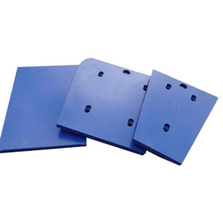
Plate Body The core load-bearing part, shaped as a vertical rectangular or trapezoidal flat plate with a thickness of 50–150 mm (depending on the model). It is made of high-strength cast steel (ZG35CrMo) or low-alloy structural steel (Q355D) with a surface hardness of ≥220 HBW to resist lateral impact loads. The upper and lower edges of the plate connect to the frame’s top and bottom plates, respectively. The inner side is machined with bearing housing bores and guide structures, while the outer side is designed with reinforcing ribs to enhance deformation resistance.
Bearing Housing Bore A circular through-hole in the upper part of the plate for mounting the eccentric shaft bearing, serving as the core functional area of the side plate. The bore diameter is designed according to the bearing model (tolerance H7), with a wall thickness ≥1/3 of the bearing outer diameter (to ensure load-bearing strength). Both ends of the bore are machined with steps (15–30 mm deep) to locate the bearing outer ring and seal cover. The inner surface roughness of the bore is Ra ≤1.6 μm (to reduce bearing wear). The coaxiality of the bearing housing bores on both side plates must be ≤0.05 mm (≤0.1 mm for large machines); otherwise, it may cause abnormal noise or overheating of the eccentric shaft during operation.
Guide Chute (Optional, for Some Models) A longitudinal chute machined in the lower inner part of the plate (2–3 mm wider than the flange on the moving jaw side) to restrict the swing trajectory of the moving jaw, ensuring movement along a preset direction. The chute surface is quenched (50–55 HRC) and coated with grease to reduce friction. The fit gap between the chute and the moving jaw is controlled at 0.5–1 mm; excessive gap may cause the moving jaw to shake, while insufficient gap may lead to jamming.
Reinforcement Structures
Annular Reinforcing Ribs: Annular ribs (rectangular cross-section, 50–100 mm wide) are cast or welded around the outer side of the bearing housing bore to enhance shear resistance around the bore and prevent deformation due to excessive force.
Longitudinal Reinforcing Ribs: Longitudinal ribs (300–500 mm apart) are welded or cast on the outer side of the plate, with a height 1.5–2 times the plate thickness. They form a grid structure with transverse ribs at the upper and lower edges, improving overall rigidity (deflection ≤0.5 mm/m).
Connection and Positioning Structures
Flange Edges: Flange edges (10–20 mm thicker than the plate) are machined on the front and rear edges of the plate for bolt connection with the front and rear walls (bolt specifications M24–M48, grade 8.8 or higher). Locating pin holes (20–40 mm in diameter) are machined on the flange surface with a fit gap ≤0.1 mm to ensure assembly precision.
Lifting Holes: φ50–φ100 mm lifting holes (threaded or through holes) are machined on the top or side of the plate for handling and installation. The area around the holes is thickened (≥40 mm) to prevent tearing.
II. Casting Process of Side Plates (Cast Steel Example)
Mold and Sand Mold Preparation
Resin sand casting (small/medium) or sodium silicate sand casting (large) is used. Wooden or foam patterns are made based on 3D models, with a 2.5%–3% shrinkage allowance (cast steel linear shrinkage 2.2%–2.8%). Sand cores are used for key areas such as bearing housing bores, with zircon powder coating (1–1.5 mm thick) applied to core surfaces to improve precision.
During sand mold assembly, symmetry of the molds for both side plates is ensured, with coaxiality deviation of bearing housing bore cores ≤0.1 mm to avoid dimensional errors in castings.
Melting and Pouring
Low-phosphorus, low-sulfur scrap steel (P≤0.03%, S≤0.02%) and alloys are melted in an electric arc furnace to 1540–1580°C. Chemical composition is adjusted (ZG35CrMo: C 0.32%–0.40%, Cr 0.8%–1.1%, Mo 0.2%–0.3%), and gas and inclusions are removed via ladle refining (hydrogen content ≤2 ppm).
A bottom-pouring system is used, with simultaneous pouring from both lower sides of the plate. Pouring temperature is 1500–1540°C, and time is 15–40 minutes (depending on weight: 1000–8000 kg) to ensure smooth filling and avoid slag entrapment or cold shuts. Risers (15%–20% of casting weight) are used for large plates to prevent shrinkage cavities.
Shakeout and Heat Treatment
Castings are shakeout after cooling below 200°C. Risers are removed by mechanical cutting, ground flush with the plate surface, and flash and sand adhesion are cleaned.
Heat treatment: Normalizing (880–920°C for 2–3 hours, air-cooled) + tempering (550–600°C for 4–5 hours, air-cooled) to homogenize the structure into pearlite + 少量 ferrite, with hardness controlled at 220–260 HBW and impact toughness ≥35 J/cm² (-20°C).
III. Machining Process of Side Plates
Rough Machining
Using the outer side of the plate as a reference, flange edges and inner surfaces are rough-milled on a gantry mill, leaving 3–5 mm finishing allowance. Flange flatness ≤1 mm/m, and perpendicularity to the plate ≤0.5 mm/100 mm.
Bearing housing bores are rough-bored on a horizontal boring machine to 5–8 mm oversize, with bore axis perpendicularity to the flange ≤0.3 mm/100 mm. Both side plates are machined simultaneously to ensure symmetry.
Semi-Finishing and Aging
Surfaces are semi-finished (1–2 mm allowance), and bores are semi-bored (1–2 mm allowance). Vibration aging (60–100 Hz for 2–3 hours) relieves machining stress (residual stress ≤100 MPa) to prevent post-finishing deformation.
Finish Machining
Bearing housing bores are finish-bored on a CNC boring machine with dual-axis synchronous tools to ensure coaxiality ≤0.05 mm (≤0.1 mm for large machines), H7 tolerance, Ra ≤1.6 μm, and step perpendicularity to the bore axis ≤0.02 mm/100 mm.
Connection holes and chutes are machined: Bolt holes (H12 tolerance) and locating pin holes (H7/m6 fit with front/rear walls) are drilled on flanges. For guide chutes, CNC milling + grinding (Ra ≤3.2 μm) ensures parallelism to the bearing bore axis ≤0.1 mm/m.
Surface Treatment and Assembly Preparation
Unmachined surfaces are sandblasted (Sa2.5) and coated with epoxy zinc-rich primer (60–80 μm) and chlorinated rubber topcoat (40–60 μm). Machined surfaces receive rust-preventive oil (large) or phosphating (small/medium).
Bearing housing bores are coated with anti-rust grease and covered with protective sleeves; threaded holes on flanges are fitted with protective plugs to prevent damage during transportation.
IV. Quality Control Process
Casting Quality Control
Visual inspection: 100% inspection for cracks, shrinkage, or misruns. Magnetic particle testing (MT) around bearing housing bores ensures no surface cracks >1 mm.
Internal quality: Ultrasonic testing (UT) for large plates (>3000 kg) prohibits ≥φ3 mm defects within 20 mm below the bearing bore; other areas allow ≤φ5 mm defects (single area ≤5 cm²).
Dimensional Accuracy Inspection
Coordinate measuring machines verify bore diameter (H7), coaxiality, perpendicularity, and flange flatness, with key deviations controlled within 50% of design tolerances.
Laser trackers check plate straightness (≤0.5 mm/m) and twist (≤0.3 mm/m) to avoid frame stress after assembly.
Hardness testing: Brinell hardness (220–260 HBW) with ≤30 HBW variation; quenched steps are tested via Rockwell (50–55 HRC).
Assembly and Operational Testing
Trial assembly: Side plates are connected to the front/rear walls, with bore coaxiality checked via mandrel (gap ≤0.05 mm) and flange fit (≥80% area with ≤0.1 mm gap).
No-load test: After assembling the eccentric shaft and bearings, 2-hour operation checks bearing temperature (≤70°C), vibration (≤0.1 mm/s), and noise for abnormalities.
With a 5–8 year service life, side plates ensure stable operation through strict quality control. Routine maintenance includes checking bore wear (repair when >0.2 mm) and bolt tightness to prevent premature failure