The flywheel is a critical transmission and energy-storage component of jaw crushers, typically mounted on both ends of the eccentric shaft. It works in conjunction with the motor pulley to drive the equipment. Its core function is to store energy using its large rotational inertia, balance periodic load fluctuations generated by the eccentric shaft during rotation, reduce impact on the motor load, and ensure stable operation of the crusher (especially by buffering energy between the "working stroke" when the movable jaw crushes materials and the "idle stroke" during return). Additionally, the flywheel transmits power, transferring motor torque to the eccentric shaft via belt drive to enable the reciprocating crushing motion of the movable jaw.
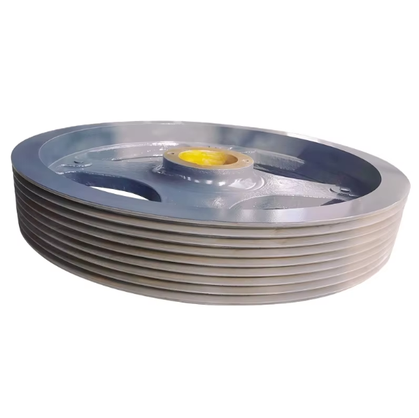
Flywheels are generally disc-shaped, with pulley grooves on the outer rim (some models integrate the flywheel and pulley). The center features a shaft hole matching the eccentric shaft, and weight-reduction holes or reinforcing ribs may be added on both sides (to balance lightness and rigidity). Their weight varies by crusher size: 50–200 kg for small machines and 500–2000 kg for large ones. The material must offer high strength and toughness to withstand frequent torque and centrifugal forces.
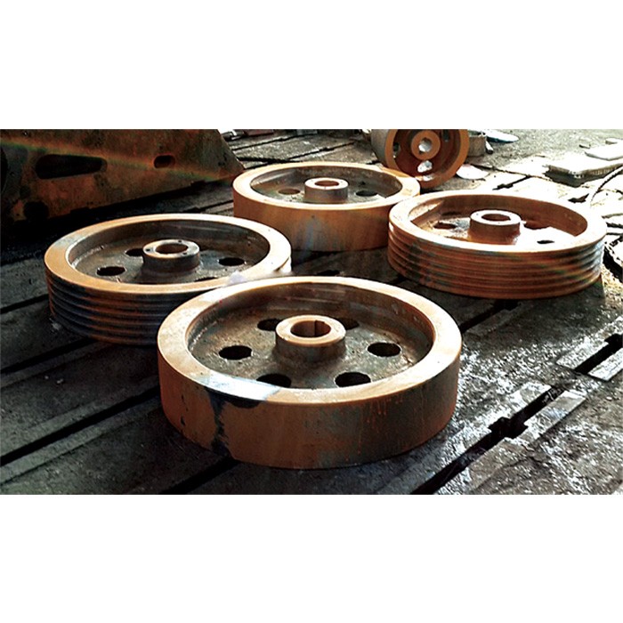
Jaw crusher flywheels are mostly produced via casting, using gray cast iron (HT250, HT300) or ductile iron (QT450-10, QT500-7). Gray cast iron, with low cost, good shock absorption, and ease of machining, is suitable for small-to-medium flywheels. Ductile iron, with higher strength (tensile strength ≥450 MPa) and excellent toughness, is used for large or high-load flywheels. The specific casting process is as follows:
Mold Preparation
Sand casting (resin sand or sodium silicate sand) is adopted. Wooden or metal patterns (including details like shaft holes, pulley grooves, and weight-reduction holes) are made based on flywheel drawings, with a 3–5 mm machining allowance reserved (considering gray cast iron’s ~1% shrinkage rate).
The sand mold is compacted to ≥85% density to ensure a smooth cavity surface, preventing sand holes on the casting. Venting grooves are added on the parting surface to avoid gas entrapment and porosity during pouring.
Melting and Pouring
Gray cast iron melting: Pig iron, scrap steel, and return scrap are proportioned, melted in a cupola or medium-frequency furnace at 1400–1450°C. Chemical composition is controlled (C: 3.2–3.6%, Si: 1.8–2.2%, Mn: 0.6–0.9%, S ≤0.12%, P ≤0.15%) to balance fluidity and strength.
Ductile iron requires spheroidizing agents (e.g., magnesium alloys, cerium alloys) and inoculants (ferrosilicon) added before tapping. Pouring is done quickly after spheroidization (to avoid spheroidization decay) at 1380–1420°C.
A bottom-pouring system ensures steady metal flow, preventing slag entrainment. Risers are used for large flywheels to feed thick sections (e.g., rims), avoiding shrinkage cavities and porosity.
Shakeout and Cleaning
The casting is shakeout after cooling to below 200°C. Risers are removed (flame cutting for large flywheels, manual knocking for small ones), and gate marks are ground smooth.
Surface sand and burrs are cleaned. Visual inspection checks for cracks or cold shuts. Weight-reduction holes and shaft holes are preliminarily cleaned.
Heat Treatment
Gray cast iron flywheels: Stress relief annealing (heated to 550–600°C, held for 2–4 hours, furnace-cooled to 200°C) eliminates casting stress, preventing deformation during machining.
Ductile iron flywheels: Normalizing (850–900°C for 1–2 hours, air-cooled) refines grains, ensuring pearlite content ≥80% and hardness 180–230 HBW.
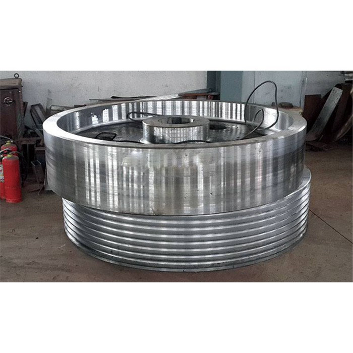
Machining precision directly affects the flywheel’s dynamic balance and transmission stability. Multiple machining steps ensure critical dimensions and geometric tolerances:
Rough Machining
Using the casting’s outer circle and end face as references, a lathe (or CNC lathe) rough-turns the rim outer circle, inner hole (matching the eccentric shaft), and both end faces, leaving a 2–3 mm finishing allowance.
Weight-reduction holes (if designed) are drilled using a radial drill, with hole diameter tolerance ±0.5 mm and surface roughness Ra ≤12.5 μm.
Semi-Finishing
Precision turning of the inner hole: Using the rough-turned outer circle as a reference, a three-jaw chuck holds the flywheel. The inner hole is turned to near design size (0.5–1 mm allowance), ensuring roundness ≤0.1 mm and fit clearance with the eccentric shaft per H7/js6 tolerance.
Pulley groove turning: For integrated flywheel-pulley designs, V-grooves are machined on the rim with depth/width tolerance ±0.2 mm, surface roughness Ra ≤6.3 μm, and groove angle deviation ≤1°.
Finishing
Final inner hole machining: Reaming or grinding (internal grinder for large flywheels) achieves H7 tolerance, surface roughness Ra ≤1.6 μm, and axis straightness ≤0.05 mm/m.
End face precision turning: Using the inner hole as a reference, a dial indicator aligns the flywheel. Both end faces are finish-turned to ensure perpendicularity to the inner hole axis ≤0.05 mm/100 mm and flatness ≤0.1 mm/m.
Preliminary dynamic balancing: A balance stand checks balance. Heavy areas are marked, and rough balancing is done by milling the rim side (removing small amounts of metal), limiting residual unbalance to ≤50 g·cm.
Surface Treatment
As a high-speed rotating component, quality control covers material, machining precision, and dynamic balance:
Raw Material and Casting Quality Control
Chemical composition inspection: A spectrometer verifies C, Si, Mn content. Tensile tests (ductile iron: tensile strength ≥450 MPa, elongation ≥10%) are conducted on samples.
Defect detection: 100% magnetic particle testing (MT) on critical areas (rim, inner hole) checks for cracks or porosity. Ultrasonic testing (UT) ensures no internal defects ≥φ3 mm.
Machining Precision Inspection
Dimensional tolerance: Calipers and micrometers check inner hole diameter, rim outer circle, and pulley groove dimensions. A dial indicator measures inner hole roundness/cylindricity (error ≤0.03 mm).
Geometric tolerance: A square and feeler gauge check end face perpendicularity. A laser interferometer verifies axis straightness.
Dynamic Balance Inspection
A hard-bearing balancing machine performs precision balancing at 50–100% of operating speed (300–600 r/min), requiring G6.3 balance grade (residual unbalance ≤10 g·cm based on weight).
After balancing, holes are drilled (or balance weights added) at heavy positions, with balance marks for alignment with the eccentric shaft during assembly.
Final Inspection Before Assembly
Visual inspection: No scratches, uniform paint, and clean inner hole (no oil or debris). Alignment with the motor pulley is checked via string line, with error ≤0.5 mm.
Trial fitting: Cold-fit testing with the eccentric shaft ensures ≥80% contact area. The flywheel should rotate freely without jamming.
These processes ensure the flywheel meets stability requirements during high-speed operation, with a service life of 8–10 years (matching the crusher). Wear or balance failure requires timely replacement or rebalancing to prevent excessive vibration or bearing overheating