The arm guard (swing arm shield) is a critical safety component in jaw crushers, installed around the swing arm to protect operators and equipment from splashing materials and prevent foreign object entanglement. It consists of a main protective plate (Q235B/Q355 steel), fixing brackets, optional buffer layers, and observation windows, with reinforcing ribs for structural rigidity.
Manufacturing involves CNC cutting, forming (bending/pressing), welding, and surface coating (epoxy + polyurethane). Quality control includes material testing, dimensional checks, weld inspection (MT), coating adhesion tests, and installation compatibility verification.
With a 1–3 year service life, it ensures safe operation by isolating moving parts and withstanding material impacts.
Detailed Introduction to the Arm Guard (Swing Arm Shield) Component of Jaw Crushers
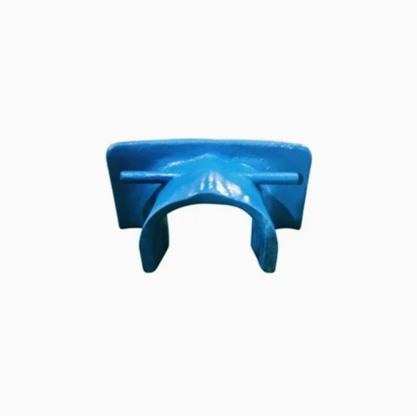
The arm guard is a critical safety protection component of jaw crushers, installed on the outer side of the swing arm (the linkage mechanism driving the swing jaw) and at the movable gap between the frame and the swing jaw. Its primary functions are to isolate moving parts from the external environment, prevent operators or equipment from being injured by splashing materials or gravel during crushing, and avoid foreign objects from being drawn into moving mechanisms (which could cause jamming). It is an essential device for ensuring safe operation and personnel protection. Its design must balance protection range, structural strength, and non-interference with the swing jaw’s movement.
I. Composition and Structure of the Arm Guard
The structure of the arm guard is customized based on the crusher model and the swing arm’s motion trajectory. Its core components and structural features are as follows:
Main Protection Plate The core protective component, typically an arc-shaped or straight steel plate. For small and medium-sized crushers, its thickness is usually 6–12 mm, while for large machines, it can reach 15–20 mm. The material is Q235B carbon structural steel (focusing on economy) or Q355 low-alloy high-strength steel (focusing on impact resistance). The shape matches the swing arm’s motion trajectory to ensure no contact within the swing jaw’s maximum swing range. It covers critical moving parts such as the swing arm, linkage-frame connections, and bearing seats.
Fixing Brackets Support structures connecting the main protection plate to the frame, usually welded from angle steel, channel steel, or steel plates. They are divided into "upper fixing brackets" (connected to the upper frame) and "lower fixing brackets" (connected to the middle or bottom of the frame). Brackets and the protection plate are bolted (for easy disassembly and maintenance), while connections to the frame are via welding or high-strength bolts to prevent loosening during equipment vibration. Long round holes (adjustment range ±5 mm) are reserved on the brackets to fine-tune the guard’s position during installation, avoiding interference with the swing arm.
Buffer/Wear Layer (in some models) Wear-resistant rubber plates (5–10 mm thick) or high manganese steel liners are glued or riveted to the side facing the crushing chamber to reduce direct impact from splashing materials and extend service life. Some arm guards feature rubber gaskets on the edges to fill gaps with the frame, preventing fine materials from infiltrating.
Observation Window (optional) Large arm guards may have rectangular observation windows in non-critical areas, inlaid with tempered glass or polycarbonate plates (≥8 mm thick). These allow operators to inspect the swing arm’s motion and internal wear without removing the guard. A metal frame around the window enhances sealing.
Reinforcing Ribs Transverse or longitudinal reinforcing ribs (spaced 200–300 mm) are welded to the back of the main plate. The ribs have an L-shaped or T-shaped cross-section, with the same thickness as the protection plate, to enhance deformation resistance and prevent dents from heavy material impacts.
II. Manufacturing Process of the Arm Guard (Focusing on the Main Protection Plate)
Although not a core load-bearing component, the arm guard requires sufficient impact resistance and structural stability. Its manufacturing primarily involves plate cutting, forming, and welding:
Raw Material Preparation
Standard steel plates (e.g., Q355) are selected with thickness tolerance controlled within ±0.5 mm. Before production, visual inspections (no cracks or delamination) and mechanical property sampling (tensile strength ≥355 MPa, elongation ≥20%) are conducted.
For arc-shaped guards, the expanded size is calculated based on the radius, with a 10–15 mm machining allowance reserved.
Cutting and Forming
CNC plasma cutting or laser cutting is used for blanking, ensuring contour dimensional tolerance ±1 mm and cutting surface roughness Ra ≤25 μm. Burrs or slag are ground smooth.
Arc forming: For thick plates, heating to 600–800°C (for low-alloy steel) followed by press bending on a mold ensures radius deviation ≤±2 mm. Cold bending (for plates ≤8 mm thick) uses a CNC press brake with multi-step bending (each step ≤15°) to prevent cracking.
Welding of Brackets and Reinforcing Ribs
Welding reinforcing ribs to the main plate: CO₂ gas shielded welding is used with a weld leg height of 5–8 mm (adjusted by plate thickness), welding current 180–220 A, and speed 30–50 cm/min. Full penetration is ensured with no cold laps, and welds are ground smooth to avoid stress concentration.
Welding fixing brackets: Fillet welds connect brackets to the guard. Tack welding (spaced 100–150 mm) ensures perpendicularity deviation ≤1 mm/100 mm. After welding, 24-hour aging treatment relieves welding stress.
Surface Treatment
Degreasing and derusting: Sandblasting (Sa2.5 grade) removes oxide scales and oil, achieving a roughness of Ra50–80 μm to enhance coating adhesion.
Coating: Epoxy primer (40–60 μm thick) and polyurethane topcoat (30–50 μm thick) are applied. 醒目的 yellow or red (for warning) is used. Paint adhesion meets Grade 2 in GB/T 9286 (no large-scale peeling in cross-cut tests).
III. Quality Control Process of the Arm Guard
The arm guard’s quality directly affects protection effectiveness and service life, requiring multi-stage controls:
Raw Material Quality Control
Steel plates must be accompanied by material certificates. Sampling includes spectral analysis (verifying chemical composition) and tensile tests (ensuring strength and elongation meet standards). Plates with laminations or cracks are rejected.
Dimensional and Forming Accuracy Inspection
Tape measures and templates check contour dimensions and radius (deviation ≤±2 mm). A square verifies perpendicularity between the guard and brackets (error ≤1 mm/100 mm). Curvature gauges ensure a gap ≥10 mm between the arc plate and the swing arm’s trajectory (no interference risk).
Welding Quality Inspection
Visual inspection of welds: No pores, slag inclusions, or undercuts (depth ≤0.5 mm), with uniform leg sizes. Critical welds (e.g., bracket-frame connections) undergo magnetic particle testing (MT) to detect surface cracks.
Load testing: A 1.5× rated impact load (simulating material impact) is applied to the guard’s center for 10 minutes. Deformation must be ≤2 mm with no weld cracking.
Surface Coating Inspection
A coating thickness gauge measures total film thickness (≥70 μm). A cross-cut tester checks adhesion (coating loss ≤5%). A 48-hour salt spray test ensures no blistering or rust.
Installation Compatibility Inspection
Trial assembly with the frame and swing arm verifies full coverage of hazardous areas. The adjustability of bracket slots (ensuring smooth fine-tuning) is checked, and no friction noise occurs during the swing jaw’s full-stroke movement.
With a typical service life of 1–3 years (depending on material impact frequency), regular maintenance of the arm guard is essential. Inspections should check coating wear, loose welds, and intact observation windows, with timely repairs or replacements to maintain safety