The front wall is a key component of jaw crushers' crushing chambers, supporting the fixed jaw plate and withstanding initial material impact. It consists of a main plate (ZG30Mn/Q355B), fixed jaw mounting structures (T-slots/bolts), connecting flanges, and reinforcement ribs, with optional wear liners and leakage-prevention lips.
Manufacturing involves cast steel casting (1460–1500°C pouring) with stress-relief annealing, followed by precision machining (flatness ≤0.1 mm/m for mounting surfaces) and surface coating. Quality control includes MT/UT for defects, hardness testing (≥200 HBW), and load trials (1.2× rated force) to ensure ≤0.2 mm deformation.
With a 3–5 year service life, it ensures stable crushing via structural rigidity and precise assembly, critical for feeding efficiency and material containment.
Detailed Introduction to the Front Wall Component of Jaw Crushers
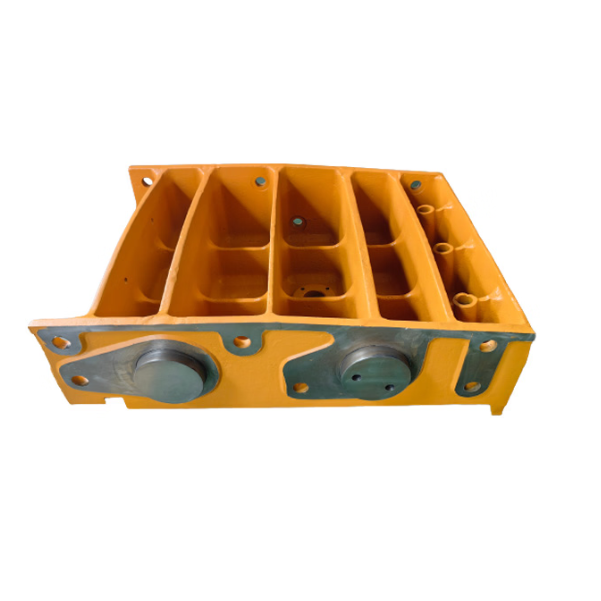
The front wall is a critical part of the crushing chamber in jaw crushers, located at the front end of the equipment. It connects directly to the fixed jaw plate and forms the fixed boundary of the crushing chamber. Its main functions include supporting the fixed jaw plate, withstanding the initial impact load of materials entering the crushing chamber, and ensuring the geometric accuracy of the crushing chamber (such as feed opening size and crushing angle) through cooperation with the swing jaw. Its structural stability directly affects crushing efficiency, the risk of material leakage, and the service life of the fixed jaw plate, making it a key component for ensuring smooth feeding and stable crushing operations.
I. Composition and Structure of the Front Wall
The design of the front wall must match the crushing chamber profile (e.g., deep chamber for fine-grained materials, shallow chamber for coarse-grained materials). It is divided into integral (small/medium-sized) and split (large-sized) types based on crusher specifications. Its core components and structural features are as follows:
Main Plate The core load-bearing structure, shaped as an inclined flat plate with an angle of 25°–35° to the horizontal plane (optimizing material falling trajectory and reducing blockage risks). The thickness ranges from 30–50 mm for small crushers to 80–120 mm for large ones. It is made of high-strength cast steel (e.g., ZG30Mn) or low-alloy structural steel (Q355B) with a surface hardness of ≥200 HBW to resist material impact and wear. The upper part of the main plate connects to the frame top plate, and the lower part extends to the middle-lower section of the crushing chamber, providing full support for the fixed jaw plate.
Fixed Jaw Plate Mounting Structure
T-slots and Bolt Holes: The inner side of the main plate (facing the crushing chamber) is machined with horizontal T-slots (width 20–50 mm) or arrayed bolt holes (spacing 150–300 mm) to secure the fixed jaw plate via T-bolts or countersunk bolts. T-slots allow lateral adjustment of the fixed jaw plate (±5 mm), while bolt holes use high-strength bolts (grade 8.8) to ensure tight connections, preventing loosening under impact loads.
Locating Bosses: 5–10 mm high bosses are provided on the edges of the main plate, matching grooves on the fixed jaw plate edges to restrict lateral displacement. Positioning accuracy must be ≤0.5 mm to avoid material jamming due to excessive gaps.
Connecting Flange A flanged structure on both sides and top of the main plate, 10–20 mm thicker than the main plate, for fixed connection to the frame (welded or bolted). The flange surface is machined with locating pin holes (diameter 16–30 mm) and connecting bolt holes (M20–M48) with a positional tolerance of ±0.5 mm to ensure coaxiality during frame assembly. Flanges of large front walls are integrally cast with the main plate, while those of small/medium front walls are connected via groove welding (leg height ≥10 mm), with welds inspected for defects via non-destructive testing.
Reinforcement Structures
Longitudinal Stiffeners: Longitudinal ribs (L-shaped or rectangular cross-section) are welded or cast on the outer side of the main plate (non-crushing chamber side) at 200–400 mm intervals. Their height is 1.5–2 times the main plate thickness to enhance bending resistance.
Corner Reinforcement Plates: Triangular reinforcement plates (10–20 mm thick) are welded at the corners of flanges and the main plate to disperse stress concentration, preventing cracks in connection areas under impact loads.
Auxiliary Protection Structures
Leakage Prevention Lip: The lower edge of the main plate is bent inward by 5–10 mm, with a gap of 3–5 mm from the swing jaw edge to prevent fine materials from leaking from both sides of the crushing chamber.
Wear-resistant Liners (Optional): For crushing high-hardness materials, high manganese steel (ZGMn13) wear-resistant liners (10–15 mm thick) can be bolted to the inner side of the main plate (areas not covered by the fixed jaw plate) to extend service life.
II. Casting Process of the Front Wall (Cast Steel Example)
Front walls are mostly made of cast steel (e.g., ZG30Mn, ZG35CrMo). The casting process ensures internal compactness and mechanical properties:
Mold and Sand Mold Preparation
Resin sand casting (small/medium) or sodium silicate sand casting (large) is used. Wooden or foam patterns are made from 3D models, with a 2.0%–2.5% casting shrinkage allowance (linear shrinkage for cast steel). Critical dimensions (e.g., flange thickness, T-slot position) reserve 3–5 mm machining allowance.
Sand mold surfaces are coated with zircon powder paint (0.8–1.2 mm thick) and dried at 200°C for 2 hours to form a smooth surface, preventing metal adhesion during pouring. Sand molds at corners of stiffeners and the main plate are rounded (R≥10 mm) to reduce casting stress concentration.
Melting and Pouring
Low-phosphorus, low-sulfur scrap steel (P≤0.03%, S≤0.02%) is melted in an electric arc furnace to 1520–1560°C. Ferromanganese (Mn 1.2%–1.5%) and ferrosilicon (Si 0.5%–0.8%) are added to adjust composition. After deoxidation (aluminum deoxidation), molten steel purity reaches over 99.9% (non-metallic inclusions ≤Grade 2).
A bottom-pouring system is used, with gates positioned at thick flange areas. Pouring temperature is 1460–1500°C, and time is 5–20 minutes (depending on front wall weight: 500 kg–5000 kg) to avoid slag entrapment or cold shuts from rapid filling.
Shakeout and Heat Treatment
Castings are shakeout after cooling below 250°C. Risers are removed by gas cutting and ground flush with the surface, and flash, burrs, and sand adhesion are cleaned.
Stress relief annealing: Castings are heated to 620–660°C, held for 4–6 hours, then furnace-cooled to 300°C and air-cooled to eliminate residual stress (≤120 MPa) and prevent deformation during subsequent processing or use.
III. Machining Process of the Front Wall
Rough Machining
Using the outer side of the main plate as a reference, the inner side (fixed jaw mounting surface) and flange connection surface are rough-milled on a gantry mill, leaving 3–5 mm finishing allowance. The flatness of the inner side is ≤1 mm/m, and the perpendicularity between the flange surface and the main plate is ≤0.5 mm/100 mm.
T-slots or bolt holes are rough-machined: T-slot blanks (2–3 mm wider than designed) are milled on a vertical mill, or bolt holes (1–2 mm larger than designed) are drilled on a radial drill.
Semi-finishing and Aging
Surfaces are semi-finished (1–2 mm allowance), and T-slots are semi-milled (0.5 mm allowance). Vibration aging (50–100 Hz for 2 hours) further relieves machining stress to avoid post-finishing deformation.
Finish Machining
Fixed jaw mounting surface: Finish-machined on a CNC mill to flatness ≤0.1 mm/m, surface roughness Ra≤6.3 μm, and tilt angle error ≤0.1° (ensuring uniform clearance with the swing jaw plate).
T-slots and threading: T-slots are finish-machined with a dedicated cutter (width tolerance ±0.1 mm), with slot bottom perpendicularity to the mounting surface ≤0.05 mm/100 mm. Bolt holes are tapped to thread accuracy 6H to ensure tight 配合 with fixed jaw bolts.
Locating pin holes: Drilled and reamed in cooperation with the frame, using H7/m6 transition fit. The positional tolerance between pin holes and bolt holes is ≤0.3 mm to ensure accurate alignment between the front wall and frame.
Surface Treatment and Assembly Auxiliary Machining
Unmachined surfaces are sandblasted (Sa2.5) and coated with epoxy zinc-rich primer (50–70 μm) and chlorinated rubber topcoat (40–60 μm) for corrosion resistance. Machined surfaces receive rust-preventive oil (large) or phosphating (small/medium, 5–8 μm film).
Edge chamfering: All sharp edges are rounded (R2–R3), and T-slot openings are chamfered (1×45°) to avoid damaging the fixed jaw plate or operators during assembly.
IV. Quality Control Process of the Front Wall
Casting Quality Control
Visual inspection: 100% inspection for cracks, shrinkage, or misruns. Stress concentration areas (e.g., stiffener-main plate joints, flange roots) undergo magnetic particle testing (MT) to ensure no surface or subsurface cracks (length ≤0.5 mm).
Internal quality: Large front walls (weight >2000 kg) require ultrasonic testing (UT). The core area of the main plate (1/2 thickness) must be free of ≥φ3 mm pores, inclusions, or shrinkage, with ≥80% inspection coverage.
Dimensional Accuracy Inspection
A coordinate measuring machine checks the flatness (≤0.1 mm/m), tilt angle (deviation ≤0.1°), T-slot position (tolerance ±0.3 mm), and bolt hole position (deviation ≤0.5 mm) of the fixed jaw mounting surface.
Deflection test: A 1.5× rated impact load (simulating material impact) is applied to the main plate center. Residual deformation is measured with a dial gauge after unloading, requiring ≤0.2 mm to ensure structural rigidity.
Mechanical Property Testing
Tensile testing: Sampling tests for cast steel properties. ZG30Mn must meet tensile strength ≥600 MPa and elongation ≥15%; Q355B must meet tensile strength ≥500 MPa and elongation ≥20%.
Hardness testing: Brinell hardness of the main plate surface (≥200 HBW) is measured, with a hardness difference ≤30 HBW on the same surface to ensure material uniformity.
Assembly Performance Verification
Trial assembly with the fixed jaw plate and frame: The fit between the fixed jaw plate and mounting surface is checked (using a 0.1 mm feeler gauge, with ≤20 mm insertion depth in ≥80% of areas). The flange fit gap between the front wall and frame is ≤0.1 mm (feeler gauge test).
Load testing: A 1.2× rated crushing force is applied for 30 minutes. Connection bolts between the front wall and frame must show no loosening (torque loss ≤5%), and no visible deformation or abnormal noise in the main plate is allowed.
Through strict structural design, manufacturing processes, and quality control, the front wall maintains stable performance under long-term material impact, with a service life of 3–5 years (depending on material hardness and maintenance frequency). Routine maintenance should include regular checks of bolt tightness, fixed jaw plate fit, and leakage prevention lip gaps. Timely repairs for wear or deformation ensure the integrity of the crushing chamber and equipment efficiency