The frame, a core load-bearing component of jaw crushers, supports key parts like the fixed jaw plate and eccentric shaft, enduring all crushing forces. It features an integral (small/medium crushers) or split (large models) structure with bearing bores, a fixed jaw mounting surface, toggle plate seat mounts, and reinforcing ribs, made of ZG270-500 cast steel or QT500-7.
Manufacturing involves sand casting (1480–1520°C pouring) with stress-relief annealing, followed by precision machining (bearing bore tolerance H7, flatness ≤0.1 mm/m). Quality control includes UT/MT for defects, tensile testing (≥500 MPa), and load trials ensuring ≤0.2 mm/m deformation under 1.2× rated load.
Critical for structural rigidity, it ensures stable crusher operation with long-term durability.
Detailed Introduction to the Frame Component of Jaw Crushers
The frame is the foundational load-bearing component of jaw crushers, acting as the "skeleton" to support core parts such as the fixed jaw plate, swing jaw, eccentric shaft, and bearing housings. It withstands all loads generated during crushing (including material impact and extrusion forces). Its structural stability directly determines the crusher’s overall rigidity, operational precision, and service life, making it a core component ensuring safe and efficient equipment operation.
I. Composition and Structure of the Frame
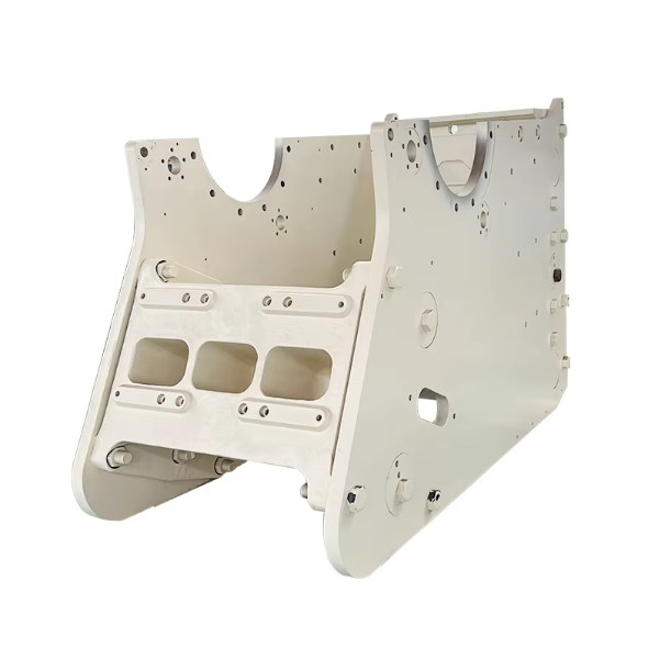
The frame is designed to balance strength, rigidity, and lightweight properties, categorized into integral and split types based on crusher size (small/medium vs. large). Its main components and structural features are as follows:
Main Frame Structure
Integral frame: Small/medium crushers (capacity ≤100 t/h) often use integral cast or welded structures, shaped like a "U" with vertical side walls (30–80 mm thick), a horizontal base plate (50–100 mm thick), and a top section connecting to the fixed jaw plate. A central bore for the eccentric shaft bearing housing is 预留,with the frame accounting for 30–40% of the total equipment weight.
Split frame: Large crushers (capacity >100 t/h) consist of upper and lower frames connected by high-strength bolts (M36–M64, grade 8.8+), facilitating transportation and on-site assembly. The upper frame supports the fixed jaw plate and eccentric shaft, while the lower frame bears the swing jaw and toggle plate seat. A locating spigot (fit clearance ≤0.1 mm) ensures assembly accuracy at the joint.
Bearing Housing Bore A circular through-hole in the frame’s side walls for mounting the eccentric shaft bearing. The bore diameter is designed per the bearing model (tolerance H7), with wall thickness ≥1/3 of the bearing outer diameter (to enhance load capacity). Step features (10–20 mm deep) at both ends locate the bearing outer ring and seal cover, with an internal surface roughness of Ra ≤1.6 μm (reducing bearing wear).
Fixed Jaw Plate Mounting Surface An inclined front surface (20°–30° from horizontal, optimizing the crushing chamber profile) with T-slots or bolt holes (150–300 mm spacing) for securing the fixed jaw plate. Flatness ≤0.5 mm/m and perpendicularity to the bearing bore axis ≤0.1 mm/100 mm ensure parallelism between the fixed and swing jaw plates.
Toggle Plate Seat Mount A concave structure on the frame’s rear wall or lower frame base, connected to the toggle plate seat via bolts or integrally cast. Its surface matches the toggle plate seat (flat or 弧形) to ensure uniform force transmission. Reinforcing ribs (20–50 mm thick) around the mount enhance impact resistance.
Reinforcement Structures
Transverse beams: Large frames feature welded or cast transverse beams (rectangular or I-shaped cross-section) between side walls (500–800 mm spacing) to prevent lateral deformation under load.
Ribs: Grid-like ribs (50–150 mm high) on the inner frame, with filleted corners (R10–R20) at rib-to-wall/base joints to avoid stress concentration.
Auxiliary Structures
Lifting holes: φ50–φ100 mm holes (threaded or through) on the top/side for handling, with reinforced surrounds (≥30 mm thick) to prevent tearing.
Discharge adjustment mounts: Bolt holes or slides on the lower frame for installing discharge gap adjusters (e.g., shim packs or wedges) to regulate product size.
II. Casting Process of the Frame (Integral Cast Steel Frame)
Frames are typically made of high-strength cast steel (ZG270-500, ZG35CrMo) or ductile iron (QT500-7 for small/medium models). The casting process ensures internal density and structural strength:
Mold and Sand Preparation
Sodium silicate or resin sand molds are used. Wooden patterns (large) or foam patterns (small/medium) are fabricated from 3D models, with 3–5% shrinkage allowance (2–2.5% linear shrinkage for cast steel).
Mold surfaces are coated with zircon powder (0.5–1 mm thick) for improved finish. Critical areas (bearing bores, mounting surfaces) use cold-hardened sand (surface hardness ≥80 Shore D) for dimensional accuracy.
Melting and Pouring
Low-P/S scrap steel and pig iron are melted in an arc furnace at 1520–1580°C. Composition is adjusted (ZG270-500: C 0.24–0.32%, Si 0.5–0.8%), and deoxidized to ≥99.9% purity (non-metallic inclusions ≤Grade 2).
A stepped gating system is used, with multi-point bottom pouring (3–5 gates for large frames) at 1480–1520°C. Pouring time is 15–40 minutes (by weight) to ensure smooth filling and avoid slag entrapment.
Shakeout and Heat Treatment
Castings are shakeout after cooling below 200°C. Risers are removed (flame-cut and ground), and surface sand/flash is cleaned.
Annealing: Heated to 650–700°C, held for 6–8 hours, then furnace-cooled to 300°C for air cooling to eliminate residual stress (≤100 MPa) and prevent post-machining deformation.
III. Machining Process of the Frame
Rough Machining
Using the base plate as a datum, gantry mills rough-mill side walls and fixed jaw mounting surfaces, leaving 5–10 mm finish allowance. Side wall parallelism ≤1 mm/m; mounting surface angle deviation ≤0.5°.
Bearing bores are rough-bored to 5–8 mm oversize on a horizontal boring machine, with bore axis perpendicularity to the mounting surface ≤0.3 mm/100 mm.
Semi-Finishing and Aging
Surfaces are semi-finished (2–3 mm allowance), and bores are semi-bored (1–2 mm allowance). Artificial aging (200–250°C for 4 hours) further relieves machining stress.
Finish Machining
Fixed jaw mounting surface: CNC gantry-milled to flatness ≤0.1 mm/m, Ra ≤6.3 μm, angle error ≤0.1°.
Bearing bores: CNC-bored to H7 tolerance with ≤0.05 mm coaxiality between sides, Ra ≤1.6 μm. Step faces at bore ends have ≤0.02 mm/100 mm perpendicularity to the bore axis.
Holes and slots: Fixed jaw bolt holes (H12 tolerance), toggle seat holes, and T-slots (±0.2 mm width) are machined, with ≤0.5 mm positional deviation from drawings.
Surface Treatment
Unmachined surfaces are sandblasted (Sa2.5) and coated with epoxy zinc-rich primer (60–80 μm) and chlorinated rubber topcoat (40–60 μm) for corrosion resistance. Machined surfaces receive rust-preventive oil (large) or phosphating (small/medium).
IV. Quality Control of the Frame
Casting Quality
Visual inspection: No cracks, shrinkage, or misruns. Critical areas (bearing bore surrounds) undergo magnetic particle testing (MT) to detect surface cracks (length ≤1 mm).
Internal quality: Large frames undergo ultrasonic testing (UT) with ≥80% coverage. Bearing bores and ribs must be free of ≥φ5 mm inclusions/gas pores.
Split frames are inspected for joint surface flatness (≤0.15 mm/m) and spigot fit clearance (≤0.1 mm).
Mechanical Properties
Tensile tests (ZG270-500: ≥500 MPa tensile strength, ≥20% elongation) and hardness checks (180–230 HBW) are performed on samples.
Water-jacketed frames undergo a 1.5× working pressure hydrostatic test for 30 minutes with no leakage.
Load Testing
A 1.2× rated crushing force is applied for 1 hour. Strain gauges measure maximum stress (≤80% of yield strength), with deformation ≤0.2 mm/m (bearing bore axis offset ≤0.03 mm).
V. Common Chinese-English Names
架体 - Frame
机架 - Crusher Frame
机座 - Machine Base
破碎机架 - Jaw Crusher Frame
主体框架 - Main Frame
支承架 - Supporting Frame
These terms are universally used in technical documents to refer to the jaw crusher’s foundational load-bearing structure