The fixed jaw plate is a stationary wear-resistant component forming one side of the crushing chamber in jaw crushers. Mounted opposite the swing jaw plate on the front of the frame, it serves as the "fixed working surface" for material crushing. During operation, the fixed jaw plate remains stationary while cooperating with the reciprocating swing jaw plate to form a periodically opening and closing crushing space, breaking materials to the desired size through extrusion and splitting. Its structural stability and wear resistance directly affect crushing efficiency, product size uniformity, and equipment operating costs.
The design of the fixed jaw plate balances wear resistance, ease of installation, and fit with the frame. Its main components and structural features are as follows:
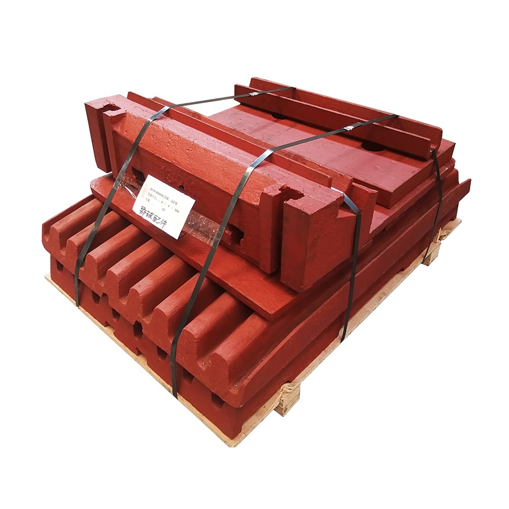
Main Body
A thick plate structure with thickness typically 50–150 mm for small-to-medium crushers and 200–300 mm for large machines. It is primarily made of high manganese steel (ZGMn13) for high-impact conditions, while high chromium cast iron (Cr26–30) may be used for low-impact scenarios. The front surface acts as the crushing 工作面,and the rear surface is the mounting face that fits the frame. The overall shape is either "straight" or "curved" (curved designs optimize the crushing chamber profile to reduce material blockage).
Toothed Working Surface
The material-contacting surface features regularly arranged teeth, commonly triangular or trapezoidal, with heights of 8–30 mm (adjusted for material hardness) and pitches of 20–60 mm, and tooth apex angles of 60°–90°. Teeth are often symmetrically arranged or staggered vertically. Symmetric designs allow reversal after one end wears, extending service life by over 50%. The toothed pattern enhances material gripping to prevent slipping and improve crushing efficiency.
Mounting Structure
The fixed jaw plate is secured to the frame via bolts or wedge blocks, so the rear surface includes:
Bolt holes/counterbores: Uniformly distributed along the plate length, with diameters 1–2 mm larger than the bolts to allow fine positional adjustment during installation.
Locating spigots/bosses: Mate with grooves on the frame to limit lateral displacement, ensuring positional accuracy relative to the swing jaw plate.
Weight-reduction slots (large plates): Rectangular or circular slots in non-load-bearing areas reduce weight without compromising structural strength.
Edge Reinforcements
The upper and lower edges are typically thicker (5–10 mm thicker than the middle section) to enhance impact resistance, preventing edge chipping from lateral material impacts. Some fixed jaw plates feature a "discharge port guard" at the bottom to guide crushed material for smooth discharge.
The fixed jaw plate endures severe impact and friction, requiring casting processes that ensure material uniformity and impact toughness. The specific process is as follows:
Mold Preparation
Resin sand casting (small-to-medium plates) or sodium silicate sand casting (large plates) is used. Wooden or foam patterns are fabricated from 3D drawings, accurately replicating teeth, bolt holes, and mounting surfaces, with a 5–8 mm machining allowance (high manganese steel has a shrinkage rate of ~2%).
Toothed areas use "split sand cores" or "integral molding" to ensure precision of tooth tips and roots (tooth height deviation ≤ 0.5 mm). Mounting surface molds are finished to ensure casting flatness error ≤ 2 mm/m.
Melting and Pouring
High manganese steel melting: Low-phosphorus (P ≤ 0.07%) and low-sulfur (S ≤ 0.05%) pig iron and scrap steel are melted in an intermediate frequency furnace at 1500–1550°C. Chemical composition is controlled (C: 1.0–1.4%, Mn: 11–14%, Si: 0.3–0.8%) to ensure a Mn/C ratio ≥ 10 (critical for austenitic structure).
Deoxidation: Ferrosilicon (0.5–1.0%) and aluminum blocks (0.1–0.2%) are added for final deoxidation, reducing oxygen content to ≤ 0.005% to prevent porosity.
Pouring: A bottom-pouring system is used with a temperature of 1400–1450°C. Large fixed jaw plates are poured in 2–3 stages (30–60 seconds apart to avoid cold shuts), with duration 3–10 minutes depending on weight, ensuring complete filling.
Shakeout and Solution Annealing
The casting is shakeout after cooling to below 200°C. Risers are removed by flame cutting, and gate marks are ground flush. Surface sand and flash are cleaned.
Solution annealing (critical step): The casting is slowly heated to 1050–1100°C (heating rate ≤ 100°C/h to prevent cracking) and held for 2–4 hours (ensuring complete carbide dissolution into austenite). It is then rapidly water-cooled (water temperature ≤ 30°C, cooling rate ≥ 50°C/s) to form a single austenitic structure with hardness ≤ 230 HBW and impact energy ≥ 180 J (-40°C).
Machining ensures working surface precision and mounting fit, preventing uneven crushing chamber gaps due to dimensional deviations. The specific process is as follows:
Rough Machining
Using the as-cast mounting surface as a reference, the working surface (excluding teeth) is rough-milled on a gantry mill, leaving a 2–3 mm finishing allowance. Flatness error is controlled ≤ 1 mm/m, and parallelism with the mounting surface ≤ 0.5 mm/m.
Bolt holes are drilled on a drilling machine per drawing specifications, with diameter tolerance ± 0.5 mm and depth 2–3 mm greater than bolt length to ensure full thread engagement.
Tooth Machining
A dedicated forming cutter is used on a CNC gantry mill to machine teeth, ensuring tooth height/pitch tolerance ± 0.5 mm and surface roughness Ra ≤ 6.3 μm. For symmetric teeth, symmetry deviation ≤ 0.3 mm (to enable reversal).
Tooth root filleting: A radius cutter trims roots (R = 2–5 mm) to avoid stress concentration and tooth root fracture.
Mounting Surface Finishing
The mounting surface is finish-milled to Ra ≤ 12.5 μm, flatness ≤ 0.5 mm/m, and perpendicularity to the working surface ≤ 0.1 mm/100 mm (verified with a dial indicator).
Locating spigots are milled to mate with the frame, with width tolerance ± 0.2 mm and depth tolerance ± 0.1 mm, ensuring ≥ 85% contact with the frame (gap ≤ 0.1 mm via feeler gauge).
Surface Treatment
Material Performance Control
Chemical composition inspection: A direct-reading spectrometer analyzes C, Mn, etc., ensuring compliance with ZGMn13 standards (Mn: 11–14%, C: 1.0–1.4%).
Mechanical property testing: Samples undergo impact testing (-40°C low-temperature impact energy ≥ 120 J) and hardness measurement (≤ 230 HBW after solution annealing).
Metallographic inspection: Microstructure analysis confirms a single austenitic phase (no network carbides, which reduce toughness).
Casting Quality Control
Visual defect inspection: 100% visual checks exclude cracks, shrinkage cavities, or misruns. Magnetic particle testing (MT) on teeth ensures no surface cracks or cold shuts.
Internal quality inspection: Ultrasonic testing (UT) on large plates prohibits ≥ φ3 mm pores or inclusions in critical areas (tooth roots, bolt holes).
Machining Accuracy Control
Dimensional tolerance inspection: Tooth profile compliance is checked with templates. A coordinate measuring machine verifies bolt hole position tolerance (± 0.2 mm).
Geometric tolerance inspection: A laser level checks working surface flatness. A square verifies perpendicularity between mounting and working surfaces.
Assembly Verification
Trial fitting: The fixed jaw plate is mounted to the frame to check tightness (bolt preload meets specifications) with no looseness when manually shaken.
Crushing test: 8-hour rated-load crushing of standard materials (e.g., granite) checks tooth wear (≤ 0.5 mm), absence of cracks/deformation, and product size deviation ≤ 5%.
Through these processes, the fixed jaw plate maintains wear resistance under high-impact conditions, with a service life of 4–8 months (adjusted for material hardness). Routine inspections of tooth wear and timely reversal/replacement ensure consistent crushing efficiency
1. Type of tooth plate
The cross-sectional structure of the tooth plate of the jaw crusher has two types: a smooth surface and a lattice surface. The latter is divided into a triangle and a trapezoid surface. In order to ensure the product size and shape, triangular or trapezoidal tooth plates are usually used.

2. The material of the tooth plate
The tooth plates used in the existing jaw crushers generally use manganese 13ZGMn13, which is characterized by surface hardening under impact load. The manganese 13ZGMn13 can form a hard and wear-resistant surface while still maintaining the original metal of its inner layer. Toughness, so it is a kind of wear-resistant material commonly used in crushers.
3. Modification plan of tooth plate
In the transformation, the working parts of the crusher are the fixed tooth plate and the movable tooth plate. The movable tooth plate is fixed on the movable jaw, and its main wear parts are mainly concentrated in the middle. In the transformation, the movable tooth plate was not modified, mainly the fixed tooth plate. After the fixed tooth plate is modified, because the fixed tooth plate is connected with the frame body, the weight of the fixed tooth plate increases, and there is no adverse effect on the work of the entire crusher.
4. The life of the tooth plate
The tooth plate bears great impact and squeezing force, so it wears very badly. In order to extend its service life, it can be studied from two aspects: one is to find high wear resistance materials from the material; the other is to reasonably determine the structural design and geometric dimensions of the tooth plate.