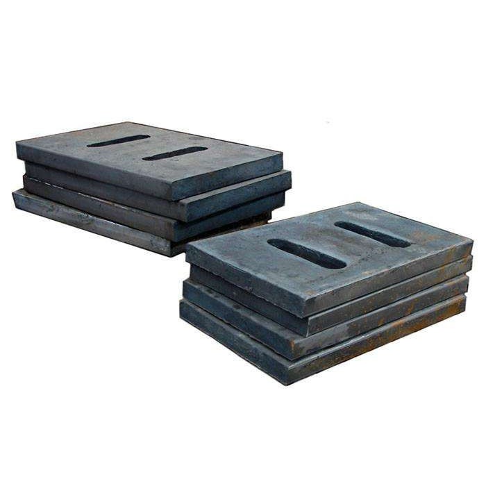
The toggle plate seat is a key load-bearing component in jaw crushers, supporting the toggle plate at the frame’s rear wall and swing jaw’s lower part to transmit crushing forces and enable the swing jaw’s oscillation. It comprises a high-strength base body (ZG35CrMo/HT350), a contact surface (spherical concave or flat groove) matching the toggle plate, and fixing structures (bolts, locating pins) with reinforcing ribs for rigidity.
Manufacturing involves resin sand casting (1480–1520°C pouring) followed by stress-relief annealing, with precision machining of the contact surface (flatness ≤0.1 mm/100 mm) and assembly holes. Quality control includes MT/UT for defects, hardness testing (≥200 HBW), and load trials to ensure ≤0.1 mm deformation under 1.2× rated load.
With a 2–3 year service life, it ensures stable force transmission and equipment safety through strict process control.
Detailed Introduction to the Toggle Plate Seat Component of Jaw Crushers
The toggle plate seat is a critical load-bearing component in jaw crushers, designed to mount and support the toggle plate. It is respectively positioned on the rear wall of the frame and the lower part of the swing jaw. Through contact with the spherical or flat ends of the toggle plate, it transmits the crushing force from the oscillating swing jaw to the fixed frame, while cooperating with the toggle plate to enable the reciprocating movement of the swing jaw. Its structural strength and assembly accuracy directly affect the efficiency of crushing force transmission and the stability of equipment operation, serving as a core auxiliary component for ensuring the crusher's overload protection function (toggle plate fracture for load relief).
I. Composition and Structure of the Toggle Plate Seat
The design of the toggle plate seat must match the shape of the toggle plate ends (spherical or flat contact) and adapt to the load requirements of different machine models. Its main components and structural features are as follows:
Base Body The core load-bearing part, divided into the "frame toggle plate seat" (fixed on the rear wall of the frame) and the "swing jaw toggle plate seat" (integrated into the lower part of the swing jaw). For small and medium-sized crushers, the base body is mostly a boss structure cast integrally with the frame/swing jaw; for large machines, a split design is adopted (connected to the frame/swing jaw via bolts). The base body is made of high-strength cast steel (ZG35CrMo) or wear-resistant cast iron (HT350) with a surface hardness of ≥200 HBW to withstand the impact and extrusion from the toggle plate.
Contact Working Surface The critical area in contact with the toggle plate ends, designed according to the toggle plate type:
Spherical concave 坑: Matches the spherical end of the toggle plate. The curvature radius of the concave 坑 is 0.5–1 mm larger than that of the toggle plate’s spherical surface, ensuring a contact area of ≥70% to reduce local stress concentration.
Flat groove: Matches the flat end of the toggle plate. The groove depth is 5–10 mm, and the bottom surface is equipped with a wear-resistant liner (high manganese steel) to enhance wear resistance. The surface roughness of the working surface must be ≤Ra12.5 μm to avoid premature wear of the toggle plate ends due to surface roughness.
Positioning and Fixing Structure
Split toggle plate seats are provided with flange edges, connected to the frame/swing jaw via 8–12 high-strength bolts (M20–M36, grade 8.8). Bolt holes are evenly distributed (spacing 100–200 mm), with a diameter 1–2 mm larger than the bolt diameter to allow minor position adjustment.
The bottom or side of the base body is equipped with positioning pin holes (diameter 20–50 mm), which cooperate with positioning pins on the frame/swing jaw to limit positioning deviation to ≤0.1 mm, ensuring alignment with the toggle plate.
Reinforcing Ribs and Weight-Reduction Structures Radial or grid-shaped reinforcing ribs (thickness 10–20 mm) are designed in the non-contact area of the base body, with rib height being 1/3–1/2 of the base body thickness to enhance overall rigidity. Large toggle plate seats may have weight-reduction holes (diameter 50–100 mm) in the internal non-loaded area, reducing weight without compromising structural strength.
Lubrication Channels (in some models) For toggle plate seats with spherical contact, φ6–φ10 mm lubrication holes are drilled at the edge of the working surface, connected to the oil circuit inside the frame. Lithium-based grease (NLGI 2) is regularly injected to reduce friction and wear between the toggle plate and the seat.
II. Casting Process of the Toggle Plate Seat
The toggle plate seat must withstand high-frequency impact loads, so the casting process must ensure material compactness and internal quality. The specific process is as follows:
Mold and Sand Mold Preparation
Resin sand casting (small and medium-sized) or sodium silicate sand casting (large-sized) is used. Wooden or foam patterns are made based on 3D models, accurately replicating the working surface shape, bolt holes, and reinforcing rib structures, with a 3–5 mm machining allowance reserved (cast steel shrinkage rate is 2–2.5%).
The sand mold for the working surface is "surface-hardened" (coated with zircon powder coating) with a coating thickness of 0.5–1 mm to prevent sand adhesion during pouring, which affects surface quality.
Melting and Pouring
Cast steel melting: Low-phosphorus and low-sulfur scrap steel (P ≤0.03%, S ≤0.02%) is selected, heated to 1550–1600°C in an electric arc furnace. Ferrosilicon and ferromanganese are added for deoxidation, and the chemical composition is adjusted (ZG35CrMo contains 0.8–1.1% Cr and 0.2–0.3% Mo) to ensure mechanical properties (tensile strength ≥600 MPa).
Pouring: A bottom-pouring system is used with a pouring temperature of 1480–1520°C. Large toggle plate seats are poured in 2–3 stages (30–60 seconds apart) to avoid cold shuts or shrinkage cavities. The pouring time is controlled at 5–15 minutes (depending on weight) to ensure complete filling of the molten metal.
Shakeout and Heat Treatment
The casting is shakeout after cooling to below 300°C. Risers are removed (by flame cutting or mechanical cutting), and burrs are ground flush with the surface.
Stress relief annealing: Heated to 600–650°C, held for 4–6 hours, then furnace-cooled to 200°C and air-cooled to eliminate casting stress (residual stress ≤150 MPa) and prevent deformation after machining.
III. Machining Process of the Toggle Plate Seat
Machining of the toggle plate seat must ensure working surface accuracy and assembly fit. The specific process is as follows:
Rough Machining
Using the non-working surface as a reference, the flange surface and the side of the base body are rough-milled on a gantry milling machine, leaving a 1–2 mm finishing allowance. The flatness of the flange surface is ≤1 mm/m, and the perpendicularity to the side is ≤0.5 mm/100 mm.
Bolt holes are drilled on a radial drilling machine according to the drawing, with a depth 5–10 mm longer than the bolt length. After tapping, the thread accuracy reaches grade 6H to ensure firm bolt connection.
Finishing of the Working Surface
Spherical concave 坑 machining: A CNC boring and milling machine with a spherical milling cutter is used to mill according to the set curvature radius. After machining, the curvature is checked with a template (deviation ≤0.5 mm), and then fine-ground with a grinding wheel (roughness Ra6.3 μm).
Flat groove machining: The bottom surface of the groove is finish-milled on a horizontal milling machine to ensure flatness ≤0.1 mm/100 mm and parallelism with the flange surface ≤0.2 mm/100 mm. Then, a wear-resistant liner is inlaid (fixed with countersunk bolts, with the liner surface flush with the groove surface).
Assembly Holes and Auxiliary Machining
Positioning pin holes are drilled and reamed in cooperation with the frame/swing jaw, using H7/m6 transition fit to ensure the positional tolerance between the pin holes and bolt holes is ≤0.3 mm.
Chamfering and deburring: All edges are rounded (R2–R3), and bolt holes are chamfered (1×45°) to avoid scratching operators or seals during assembly.
IV. Quality Control Process of the Toggle Plate Seat
Casting Quality Control
Visual inspection: 100% visual inspection is performed to ensure no cracks, shrinkage cavities, or insufficient pouring. Critical areas (around the working surface) undergo magnetic particle testing (MT) to check for surface cracks.
Internal quality: Large toggle plate seats undergo ultrasonic testing (UT). The core area (20 mm below the working surface) must be free of pores or inclusions with an equivalent diameter ≥φ3 mm.
Material and Mechanical Property Inspection
Spectral analysis: Verifies the chemical composition of ZG35CrMo (Cr:0.8–1.1%, Mo:0.2–0.3%) to ensure compliance with standards.
Hardness testing: A Brinell hardness tester checks the hardness of the working surface (≥200 HBW), with a hardness difference of ≤30 HBW on the same surface.
Dimensional Accuracy Inspection
A coordinate measuring machine checks the curvature radius and groove depth of the working surface (tolerance ±0.5 mm).
A dial indicator checks the flatness of the flange surface (≤0.5 mm/m) and perpendicularity (≤0.1 mm/100 mm) to ensure close fit with the frame/swing jaw.
Assembly and Performance Verification
Trial assembly test: Assembled with the toggle plate, frame, and swing jaw to check the contact area between the toggle plate and the working surface (detected with red lead powder, contact rate ≥70%). No jamming or abnormal noise occurs when the toggle plate swings.
Load-bearing test: A 1.2× rated working load is applied (for 1 hour) to check the deformation of the working surface (≤0.1 mm) and ensure no bolt loosening (torque loss ≤5%).
Through strict process control, the toggle plate seat can ensure stable support and force transmission of the toggle plate, with a service life of 2–3 years (depending on material hardness). In daily maintenance, the wear of the working surface should be checked regularly (replace or repair when wear exceeds 2 mm), and bolts should be tightened (checked every 100 hours of operation) to avoid equipment vibration or component damage due to loosening