The rear wall, a key load-bearing component in jaw crushers, supports the toggle plate seat and withstands impact forces from the swing jaw via the toggle plate. Constructed from ZG35SiMn/Q355D, it comprises a main wall plate, toggle seat mounting features (recess/boss with bolt arrays), reinforcement ribs, and auxiliary structures (inspection holes, lifting lugs).
Manufacturing involves cast steel casting (1500–1540°C pouring) with normalizing+tempering, followed by precision machining (toggle seat flatness ≤0.08 mm/m) and surface coating. Quality control includes MT/UT for defects, mechanical testing (tensile strength ≥550 MPa), and static load trials (1.5× rated load, deformation ≤0.1 mm/m).
With a 4–6 year service life, it ensures stable force transmission and crusher rigidity through robust design and strict process control.
Detailed Introduction to the Rear Wall Component of Jaw Crushers
The rear wall is a critical load-bearing component at the rear of a jaw crusher’s frame, working with the front wall and side walls to form the enclosed frame structure. Its primary functions include supporting the toggle plate seat, withstanding reverse impact forces transmitted by the swing jaw via the toggle plate, and defining the rear boundary of the crushing chamber to prevent material spillage from the rear. The structural strength and stability of the rear wall directly affect the crusher’s force transmission efficiency and overall rigidity, making it essential for ensuring long-term stable operation.
I. Composition and Structure of the Rear Wall
Designed to match the frame type (integral or split) and load characteristics, the rear wall is categorized into straight-plate (small/medium-sized) and arc-reinforced (large-sized) types based on crusher specifications. Its main components and structural features are as follows:
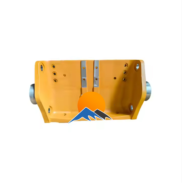
Main Wall Plate The core load-bearing part, shaped as a vertical or slightly inclined plate (large models tilt backward by 3°–5° to optimize force flow). Thickness ranges from 40 mm (small) to 120 mm (large). It is made of high-strength cast steel (ZG35SiMn) or low-alloy structural steel (Q355D) with a surface hardness of ≥220 HBW to resist cyclic impact loads from the toggle plate. The upper part connects to the frame top plate, and the lower part is welded or bolted to the base plate, forming a complete force transmission path.
Toggle Plate Seat Mounting Structure
Recess/Boss: A recess (10–30 mm deep) or boss (5–15 mm high) matching the toggle plate seat is designed in the middle of the main wall plate (aligned with the swing jaw toggle seat). The perpendicularity between the recess/boss center and the front wall’s fixed jaw mounting surface must be ≤0.1 mm/100 mm to ensure the toggle plate’s force direction aligns with the crushing force axis.
Bolt Hole Array: 4–8 circumferentially distributed bolt holes (M24–M48) are machined around the recess/boss with a positional tolerance of ±0.3 mm. High-strength bolts (grade 10.9) secure the toggle plate seat to prevent displacement under impact loads.
Reinforcement Ribs
Transverse Ribs: T-shaped or I-shaped transverse ribs are welded or cast on the outer side (non-crushing chamber side) of the main wall plate at 300–500 mm intervals. Their height is 2–3 times the wall thickness to enhance shear resistance.
Perimeter Reinforcement Frame: A rectangular reinforcement frame (15–30 mm thick) is welded at the edges connecting the main wall plate to the top plate, base plate, and side walls, dispersing stress concentration to avoid edge cracking.
Auxiliary Structures
Inspection Hole: A circular or rectangular inspection hole (150–300 mm in diameter/side length) with a removable cover is provided in the middle of large rear walls for checking toggle plate wear and internal chamber conditions. Hole edges are rounded (R≥10 mm) to prevent stress concentration.
Lifting Lugs: Lifting lugs (20–40 mm thick) with 30–80 mm diameter holes are welded to the top or sides for handling and installation. Welds between lugs and the wall plate undergo non-destructive testing.
II. Casting Process of the Rear Wall (Cast Steel Example)
Sand Mold and Pattern Preparation
Resin sand self-hardening molds are used. Foam lost-foam patterns (small/medium) or wooden patterns (large) are fabricated from 3D models with a 2.5%–3% shrinkage allowance (cast steel linear shrinkage: 2.2%–2.8%).
High-precision sand cores are used for critical areas (toggle seat recess, bolt hole peripheries). Core surfaces are coated with ceramic paint (1–1.5 mm thick) and baked (150°C for 3 hours) to form a high-strength layer ensuring dimensional accuracy.
Melting and Pouring
High-quality scrap steel and alloys are melted in an intermediate frequency induction furnace to 1540–1580°C. Composition is adjusted (ZG35SiMn: C 0.32%–0.40%, Si 1.1%–1.4%, Mn 1.1%–1.4%) and refined in an LF furnace to remove gases and inclusions, achieving ≥99.95% purity.
A step gating system is used, with simultaneous pouring from both bottom sides. Pouring temperature is 1500–1540°C, and time is 10–30 minutes (depending on weight: 800–8000 kg) to ensure smooth filling and avoid slag entrapment.
Shakeout and Heat Treatment
Castings are shakeout after cooling below 200°C. Risers are mechanically cut and ground flush, with flash and sand adhesion removed.
Normalizing + tempering: Heated to 880–920°C for 2–3 hours, air-cooled, then tempered at 550–600°C for 4–5 hours and air-cooled. This homogenizes the structure (pearlite + ferrite) to 220–260 HBW with impact toughness ≥30 J/cm².
III. Machining Process of the Rear Wall
Rough Machining
Using the inner side (facing the crushing chamber) as a reference, the outer surface and perimeter connecting surfaces are rough-milled on a gantry mill, leaving 3–5 mm finishing allowance. Outer surface flatness ≤1 mm/m; perpendicularity to the base plate ≤0.5 mm/100 mm.
The toggle seat recess is rough-milled on a vertical mill to 2–3 mm deeper than designed, with center deviation from the wall plate centerline ≤1 mm.
Semi-finishing and Stress Relief
Surfaces are semi-finished (1–2 mm allowance) and bolt holes are drilled (1–2 mm oversize). Thermal aging (250–300°C for 6 hours) relieves machining stress.
Finish Machining
Toggle seat mounting surface: CNC bored and milled to flatness ≤0.08 mm/m, Ra≤3.2 μm, and parallelism to the front wall’s fixed jaw surface ≤0.15 mm/m.
Bolt holes and threading: Precision-drilled on a coordinate boring machine and tapped to 6H thread accuracy. Positional tolerance between bolt holes and recess center ≤0.2 mm.
Inspection and lifting holes: Inspection holes are plasma-cut and bored (H12 tolerance) with rounded edges (R5–R10). Lifting holes are bored to H11 tolerance with threading (large) or reinforced sleeves (small/medium).
Surface Treatment and Assembly
Unmachined surfaces are sandblasted (Sa2.5) and coated with epoxy primer (60–80 μm) and polyurethane topcoat (40–60 μm). Machined surfaces receive rust-preventive oil (large) or galvanizing (small/medium).
Trial assembly with the frame: Checks fit with side walls (gap ≤0.3 mm) and marks bolt hole positions to ensure frame tightness.
IV. Quality Control of the Rear Wall
Casting Quality
Visual inspection: No cracks, shrinkage, or misruns. 100% magnetic particle testing (MT) on toggle seat areas ensures no surface/subsurface cracks (length ≤0.3 mm).
Internal quality: Ultrasonic testing (UT) for large rear walls (>3000 kg) covers full thickness, with no ≥φ4 mm defects in ≥95% of the area.
Dimensional Accuracy
Coordinate measuring machines verify flatness, positional tolerance, and perpendicularity of the toggle seat surface (±0.1 mm tolerance).
Laser trackers check straightness (≤0.5 mm/m) and perpendicularity (≤0.1 mm/100 mm) to avoid force transmission errors.
Impact testing: -20°C impact energy ≥27 J (ZG35SiMn) for low-temperature resistance.
Assembly and Load Testing
Trial assembly with the toggle seat: Checks fit (0.05 mm feeler gauge insertion ≤10 mm). Post-bolt tightening, flatness change ≤0.05 mm.
Static load test: 1.5× rated load applied for 1 hour shows deformation ≤0.1 mm/m with no residual deformation; bolt torque loss ≤3%.
With a 4–6 year service life (depending on material hardness and maintenance), the rear wall ensures stable performance through strict manufacturing controls. Routine checks of bolt tightness and toggle seat surface wear (repair when >1 mm) maintain force transmission integrity