The tension rod is a key auxiliary component in jaw crushers, connecting the swing jaw’s lower part to the frame, and functioning to tension the toggle plate and absorb impacts via a spring. It comprises a high-strength rod body, tension spring (60Si2Mn), adjusting nut, and connecting pins, with materials like 40Cr (tensile strength ≥800 MPa) for the rod.
Manufacturing involves forging and precision machining of the rod (with heat treatment to 240–280 HBW), spring coiling/heat treatment (38–42 HRC), and strict quality checks (MT/UT for defects, dimensional verification, and tension testing).
Quality control ensures stable performance under load, with a 1–2 year service life, critical for crusher safety and operational stability.
Detailed Introduction to the Tension Rod Component of Jaw Crushers
The tension rod is a critical auxiliary load-bearing component in jaw crushers, installed between the lower part of the swing jaw and the rear wall of the frame. It maintains constant tension to ensure the toggle plate remains tightly seated in the toggle seats of the swing jaw and frame, while cooperating with a spring to absorb impact vibrations during crushing. It is essential for stabilizing the crusher’s operation and providing overload protection, directly influencing the stability of the crushing gap and equipment safety.
I. Composition and Structure of the Tension Rod
The tension rod’s design balances tension transmission efficiency and buffering performance, with key components and structural features as follows:
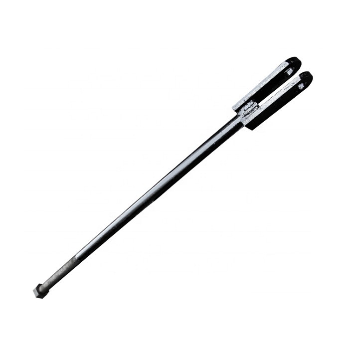
Tension Rod Body A long rod made of high-strength round steel or forged steel, with diameters typically 30–80 mm for small-to-medium crushers and 100–150 mm for large machines. One end is machined with external threads (for connecting the adjusting nut), and the other features an annular or fork-shaped lug (connected to the lower swing jaw via a pin). The lug hole diameter must precisely match the pin to ensure smooth rotation.
Tension Spring A cylindrical helical spring sleeved over the rod body, made of high-strength spring steel (e.g., 60Si2Mn). The spring wire diameter ranges from 8–30 mm, with 5–15 active coils. Both ends fit against spring seats, generating tension through pre-compression. During operation, it absorbs impact energy via deformation, buffering vibrations from the swing jaw’s oscillation.
Adjusting Nut and Washers A hexagonal nut (45# steel or 35CrMo) matching the threaded end of the rod, used to adjust spring preload (by tightening/loosening to change compression). Wear-resistant washers (e.g., quenched steel) are typically placed between the nut and spring seat to reduce friction.
Spring Seats and Retaining Rings Circular or annular parts (spring seats) at both ends of the spring position it and transmit force. A shoulder or retaining ring near the lug end prevents spring detachment during tensioning.
Pin and Cotter Pin A cylindrical pin (40Cr) connecting the lug to the swing jaw, surface-quenched (50–55 HRC), secured with a cotter pin or circlip for reliable connection.
II. Manufacturing Process of the Tension Rod Body
The rod body withstands constant tension and alternating loads, using 45# steel (quenched-tempered) or 40Cr (quenched-tempered), with manufacturing focused on forging and machining:
Raw Material Preparation and Forging
High-quality round steel billets (10–15 mm larger than the finished diameter) are inspected for internal cracks via non-destructive testing.
Heated to 850–1000°C for free forging, with drawing and upsetting to form the lug (fork-shaped lugs require post-forging cutting). The forging ensures continuous grain flow, free of folds or overheating.
Normalized (860–880°C, air-cooled) to relieve stress, with hardness 180–220 HBW for improved machinability.
Rough Machining
The rod’s outer circle is rough-turned on a lathe or CNC lathe, leaving 1–2 mm finishing allowance. The threaded end’s positioning step is turned, ensuring end-to-axis perpendicularity ≤ 0.1 mm/100 mm.
The lug hole is milled or drilled: Fork-shaped lugs are milled for symmetry, with 0.5–1 mm machining allowance; hole axis-to-rod axis perpendicularity ≤ 0.1 mm/100 mm.
Heat Treatment
Quenching and tempering: Heated to 840–860°C for oil quenching, then tempered at 550–580°C to form tempered sorbite, achieving tensile strength ≥ 800 MPa, yield strength ≥ 600 MPa, and hardness 240–280 HBW.
Induction hardening for the lug hole and threaded end: Surface hardness 45–50 HRC, with a 2–5 mm hardened layer for wear resistance.
Finishing
The rod’s outer circle is precision-turned to design dimensions (IT7 tolerance, Ra ≤ 1.6 μm). Threads are rolled or turned to 6g precision, with intact, burr-free profiles.
The lug hole is precision-bored to H7 tolerance, Ra ≤ 0.8 μm, roundness ≤ 0.01 mm, and axis-to-rod axis perpendicularity ≤ 0.05 mm/100 mm.
III. Manufacturing Process of the Tension Spring
Coiling
60Si2Mn spring wire (diameter tolerance ±0.05 mm) is coiled on a spring coiling machine, ensuring outer diameter tolerance ±0.5 mm, uniform pitch (deviation ≤ 0.3 mm), and correct free length.
Heat Treatment
Quenching: Heated to 860–880°C for oil quenching (hardness 45–50 HRC). Tempering: 380–420°C for 2 hours to form tempered troostite, with hardness 38–42 HRC, balancing elastic limit and toughness.
Surface Treatment
Shot peening: Surface 强化 with 0.3–0.8 mm steel shots to improve fatigue life (≥30% increase).
Anti-corrosion treatment: Zinc plating or phosphating + painting (8–12 μm coating), with salt spray resistance ≥48 hours.
IV. Quality Control Process for Tension Rod Components
Tension Rod Body Quality Control
Material inspection: Spectral analysis verifies composition (e.g., 40Cr with 0.8–1.1% Cr). Tensile tests confirm strength (≥800 MPa).
Non-destructive testing: Magnetic particle testing (MT) for surface cracks on the rod and lug; fluorescent testing for thread root micro-cracks.
Mechanical performance: Sampling for pressure testing (force deviation ≤ 5% at rated compression); fatigue testing (1 million cycles) with no fracture or permanent deformation > 2%.
Trial assembly: After assembling components, check spring compression (15–25% of free length). Verify lug-pin fit (H8/f7 tolerance) for smooth rotation.
Tension testing: Apply 1.2× rated tension for 1 hour, checking for plastic deformation (elongation ≤ 0.1%) or thread stripping.
Overall Performance Verification
Commissioning: 4-hour rated-load operation checks temperature (≤60°C), vibration (amplitude ≤ 0.1 mm), and no abnormal noise.
Overload testing: 1.5× rated load confirms spring buffering effectiveness, with no damage to the rod or connections.
With strict process control, tension rods ensure stable toggle plate seating and impact absorption, with a 1–2 year service life (springs require regular replacement). Routine maintenance includes checking spring preload and thread tightness to prevent toggle plate detachment or gap irregularities