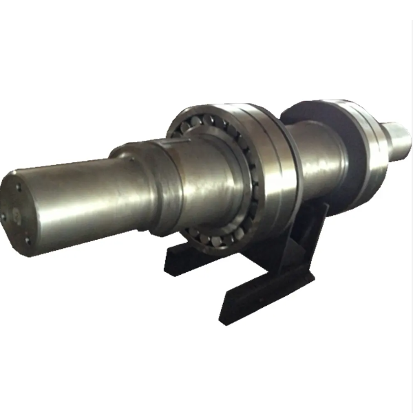
The eccentric shaft, a core component of jaw crushers, converts rotational motion into the swing jaw's reciprocation via its eccentric structure, comprising main/eccentric shaft necks, a shaft body, and transition fillets. Made of high-strength alloys (e.g., 40CrNiMo), it undergoes forging (or casting for small models), precision machining (grinding to IT6 tolerance), and heat treatment (quenching/tempering) for strength (tensile strength ≥800 MPa).
Quality control includes material composition checks, UT/MT for internal/surface defects, and dynamic balance testing (residual unbalance ≤10 g·cm). With a 5–8 year service life, it ensures stable crusher operation under high loads.
Detailed Introduction to the Eccentric Shaft Component of Jaw Crushers
The eccentric shaft is the "heart" component of a jaw crusher, mounted in the bearing housing of the frame. One end connects to the flywheel, and the other receives power from the motor via a pulley. Its eccentric structure drives the swing jaw to perform periodic reciprocating motion during rotation, serving as the core power transmission component for material crushing. The eccentric shaft must withstand enormous bending stress, torque, and impact loads, thus requiring extremely high material strength, machining precision, and structural stability.
I. Composition and Structure of the Eccentric Shaft
The structural design of the eccentric shaft balances force transmission efficiency and fatigue resistance. Its main components and structural features include:
Shaft Necks: Divided into the main shaft neck and eccentric shaft neck. The main shaft neck is a cylindrical part matching the frame's bearing housing, serving as the rotation center, requiring high cylindricity and surface precision. The eccentric shaft neck connects to the swing jaw bearing, with its axis offset from the main shaft neck's axis by an eccentricity (typically 1/4–1/3 of the shaft diameter). This eccentricity converts rotational motion into the swing of the movable jaw.
Shaft Body: The intermediate part connecting the main shaft neck and eccentric shaft neck, often stepped or cylindrical. Large eccentric shafts may have weight-reduction grooves on the shaft body (reducing weight without compromising strength). Some shaft bodies feature keyways for positioning keys of flywheels or pulleys.
Transition Fillets: Connections between the main shaft neck, eccentric shaft neck, and shaft body use large-radius transition fillets (usually R ≥ 5 mm) to reduce stress concentration and prevent fatigue fracture (these are structurally weak areas).
End Faces: Both end faces of the shaft are machined flat to serve as positioning references for flywheels and pulleys. Some end faces have center holes (for thimble positioning during machining).
The eccentric shaft is typically made of high-strength alloy structural steel. Small-to-medium crushers use 45# steel (after quenching and tempering), while medium-to-large machines adopt 40CrNiMo, 35CrMo, or other alloy steels (forged and tempered), ensuring tensile strength ≥ 800 MPa, yield strength ≥ 600 MPa, and impact energy (-20°C) ≥ 40 J.
II. Casting Process of the Eccentric Shaft
Eccentric shafts are mostly produced via forging (casting 难以满足高强度要求), but casting is used for some small, simple equipment. Details of the casting process are as follows:
Mold Preparation
Sand casting (resin sand) is used. Wooden or metal patterns are made based on the shaft structure, with an 8–12 mm allowance for forging/machining (accounting for casting shrinkage and subsequent processing needs).
The mold cavity is equipped with a reasonable gating and riser system to ensure full filling of molten metal. Large shafts use stepwise pouring to avoid shrinkage cavities and porosity.
Melting and Pouring
High-quality pig iron and scrap steel with low phosphorus and sulfur content are melted in a medium-frequency furnace, producing alloy cast steel (e.g., ZG35CrMo) with controlled chemical composition (C: 0.32–0.40%, Cr: 0.8–1.1%, Mo: 0.15–0.25%).
Pouring temperature is controlled at 1520–1560°C, using bottom pouring to ensure stable filling and prevent gas entrainment or inclusions.
Shakeout and Heat Treatment
The casting is shakeout after cooling to below 300°C. Risers are removed, and annealing is performed (heated to 650–700°C, held for 4–6 hours, then slowly cooled) to eliminate casting stress.
After rough machining, quenching and tempering are conducted: heating to 850–880°C for oil quenching, followed by tempering at 550–580°C to obtain a tempered sorbite structure with hardness 220–260 HBW and tensile strength ≥ 700 MPa.
III. Manufacturing Process of the Eccentric Shaft (Forged Parts)
Forging Process
High-quality alloy structural steel billets (e.g., 40CrNiMo) are heated to 1100–1200°C and subjected to free forging, using drawing and upsetting processes to form the shape, ensuring internal density and freedom from forging cracks.
Spheroidizing annealing (held at 780–800°C, slowly cooled) is performed after forging to reduce hardness and improve machinability.
Rough Machining
The main shaft neck, eccentric shaft neck, and shaft body are rough-turned on a lathe or CNC lathe, leaving a 3–5 mm finishing allowance, with diameter tolerance controlled at ±1 mm.
Center holes are drilled in the shaft ends as positioning references for subsequent processing.
Semi-Finishing
Using center holes for positioning, the main and eccentric shaft necks are finish-turned to near-design dimensions (0.5–1 mm grinding allowance remaining), ensuring cylindricity ≤ 0.1 mm and eccentricity deviation ≤ 0.05 mm.
Keyways are milled: machined on the shaft body or ends with width tolerance ±0.05 mm, depth tolerance ±0.1 mm, and groove bottom roughness Ra ≤ 6.3 μm.
Finishing
Grinding of main and eccentric shaft necks: External cylindrical grinding machines are used to achieve IT6 dimensional tolerance, surface roughness Ra ≤ 0.8 μm, roundness ≤ 0.005 mm, and axis straightness ≤ 0.01 mm/m.
Precision grinding of end faces: Ensuring perpendicularity to the axis ≤ 0.02 mm/100 mm.
IV. Quality Control Process of the Eccentric Shaft
Material Inspection
Spectral analysis of raw materials is conducted before forging/casting to verify chemical composition compliance. Tensile and impact tests are performed on samples to ensure mechanical properties meet standards (e.g., 40CrNiMo after tempering requires impact energy ≥ 60 J).
Internal Quality Testing
100% ultrasonic testing (UT) is performed on forgings, prohibiting internal defects ≥ φ2 mm. Magnetic particle testing (MT) is applied to stress concentration areas such as shaft neck transition fillets to ensure no surface cracks.
Machining Precision Inspection
Shaft neck diameters are measured with micrometers, and roundness/cylindricity with dial indicators. Eccentricity is checked with an eccentricity gauge, requiring deviation within ±0.03 mm of the design value.
A coordinate measuring machine verifies keyway position accuracy, ensuring symmetry error with the axis ≤ 0.05 mm.
Pre-Assembly Verification
Dynamic balance testing is conducted (rotational speed ≥ 1500 r/min) with residual unbalance ≤ 10 g·cm. Trial assembly with bearings and flywheels ensures proper fit clearance (H7/js6 for main shaft neck and bearing).
Through strict process control, the eccentric shaft maintains stable performance under long-term high-load operation, with a service life of 5–8 years (depending on material hardness and maintenance frequency), making it a core component ensuring continuous operation of jaw crushers