The hydraulic system in jaw crushers, critical for adjusting discharge gaps and overload protection, comprises power sources (hydraulic pumps, motors), actuators (adjustment/safety cylinders), control components (valves, pressure transducers), auxiliaries (pipes, filters), and L-HM 46# hydraulic oil, operating at 16–25 MPa.
Core cylinder manufacturing involves precision boring (Ra≤0.8 μm), chrome-plated piston rods (50–55 HRC), and assembly with strict sealing. Quality control includes pressure testing (1.5× working pressure), oil cleanliness (≤NAS 7), and performance checks (overload relief in 0.5s).
With MTBF ≥3000 hours under proper maintenance (oil replacement every 2000 hours), it ensures efficient, safe crusher operation via rapid response and stable pressure control.
Detailed Introduction to the Hydraulic System of Jaw Crushers
The hydraulic system of a jaw crusher is a core auxiliary system in modern large-scale or automated jaw crushers. Its main functions include adjusting the crushing gap (discharge opening size), providing overload protection (automatically relieving pressure when encountering uncrushable materials), and assisting in the reset of the swing jaw. Compared with traditional shim adjustment methods, the hydraulic system offers advantages such as convenient adjustment, rapid response, and precise protection, making it widely used in crushing production lines handling hard materials or requiring high automation.
I. Composition and Structure of the Hydraulic System
The hydraulic system consists of five parts: power source, actuators, control components, auxiliary components, and working medium. The specific structure and functions are as follows:
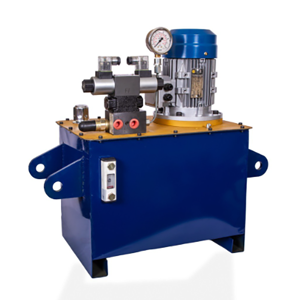
Power Source Components
Hydraulic Pump: The core power unit of the system, mostly axial piston pumps or gear pumps, which convert the mechanical energy of the motor into hydraulic energy. The working pressure is usually 16–25 MPa, and the flow rate is set according to the requirements of the actuators (e.g., 10–30 L/min).
Motor: Drives the hydraulic pump, with power matching the pump (e.g., 5.5–15 kW). It uses a three-phase asynchronous motor with overload protection.
Oil Tank: Stores hydraulic oil (capacity 3–5 times the system flow, e.g., 100–500 L) and functions in heat dissipation and impurity precipitation. It contains internal partitions (separating oil return and suction areas), a suction filter (filtration accuracy 100 μm), and a liquid level gauge.
Actuators
Adjustment cylinders (2–4, symmetrically arranged): Connect the swing jaw and frame, adjusting the position of the swing jaw through expansion to precisely control the discharge opening gap (adjustment accuracy ±0.5 mm).
Safety cylinders (1–2): Connected in parallel to the adjustment cylinder oil circuit. When uncrushable materials enter, the pressure in the cylinder rises sharply, and the pressure relief valve releases pressure to avoid equipment damage.
Hydraulic Cylinder: The core component for linear motion, divided into adjustment cylinders and safety cylinders:
Piston and Piston Rod: Moving parts inside the cylinder. The piston is made of wear-resistant cast iron (HT300), and the piston rod surface is chrome-plated (thickness 0.05–0.1 mm) with hardness ≥50 HRC to ensure wear resistance and corrosion protection.
Control Components
Relief Valve: Sets the maximum system pressure (e.g., 20 MPa). It relieves pressure when the pressure exceeds the threshold to protect pumps, cylinders, and other components from overload damage.
Directional Valve: Mostly solenoid directional valves, controlling the flow direction of hydraulic oil to realize the expansion and contraction of the cylinder (switching direction when adjusting the discharge opening).
Pressure Transducer: Monitors system pressure in real-time (accuracy ±0.5% FS) and feeds signals back to the control system for automatic pressure relief or alarm.
Throttle Valve: Adjusts the expansion speed of the cylinder to ensure stable adjustment of the discharge opening (speed 0.5–2 mm/s).
Auxiliary Components
Hydraulic Pipes: High-pressure hoses (working pressure ≥30 MPa) or seamless steel pipes (φ10–φ25 mm) connecting various components. Pipe joints are ferrule-type or flange-type (to ensure no leakage).
Filters: Include suction filters (protecting the pump), return oil filters (filtration accuracy 20 μm, protecting the entire system), and high-pressure filters (installed at the cylinder inlet to prevent impurities from scratching the cylinder wall).
Cooler: Mostly air-cooled or water-cooled. It starts when the oil temperature exceeds 55℃, controlling the oil temperature within 30–50℃ (to avoid reduced oil viscosity).
Accumulator: Stores hydraulic energy, stabilizes pressure during system pressure fluctuations (e.g., quickly replenishing pressure after safety cylinder relief), and reduces frequent starts/stops of the pump.
Working Medium
Anti-wear hydraulic oil (e.g., L-HM 46#) is used, with good oxidation resistance, anti-foaming properties, and low-temperature fluidity (viscosity index ≥140), ensuring stable operation in -10–60℃ environments.
II. Manufacturing Process of Core Components in the Hydraulic System
The manufacturing processes of core components (hydraulic cylinders, pumps, valves) vary significantly. The following focuses on the manufacturing process of the key actuator "hydraulic cylinder":
Cylinder Barrel Processing
Material: 27SiMn or 45# seamless steel pipe (wall thickness 8–20 mm). Rough turning of the outer circle and inner hole (reserving 1–2 mm machining allowance).
Precision Boring of Inner Hole: Processed on a deep hole boring machine to ensure inner diameter tolerance H9, surface roughness Ra≤0.8 μm, and cylindricity ≤0.02 mm/m (to avoid piston jamming).
Outer Circle Grinding: Ensure coaxiality between the outer circle and inner hole ≤0.03 mm, and perpendicularity between the flange faces at both ends and the axis ≤0.02 mm/100 mm.
Piston Rod Processing
Material: 40Cr, forged and tempered (hardness 28–32 HRC). Surface quenching of the piston rod head and guide section (hardness 50–55 HRC).
Precision Grinding of Outer Circle: Tolerance f7, surface roughness Ra≤0.4 μm, straightness ≤0.05 mm/m. Hard chrome plating (thickness 0.05–0.1 mm, porosity ≤3 pores/cm²), followed by polishing to Ra≤0.2 μm.
Piston and End Cover Processing
Piston: Made of HT300 or ductile iron QT500-7. After turning, a polyurethane seal ring (Y-shaped or U-shaped cross-section) is installed on the outer circle, ensuring a fit gap of 0.05–0.1 mm with the cylinder barrel inner hole.
End Cover: Cast steel (ZG230-450). A seal groove (for installing O-rings or combined seals) is processed, and the threaded hole (connecting oil pipes) has a precision of 6H to ensure no leakage.
Assembly Process
Cleaning: All parts are cleaned with kerosene to remove iron filings and oil stains. The inner wall of the cylinder barrel is wiped with silk cloth (to avoid scratching the chrome plating).
Assembly: Install the piston, piston rod, end cover, and seals in sequence, ensuring no distortion of the seal ring (lip facing the pressure oil side). The coaxiality between the guide sleeve and the piston rod ≤0.05 mm.
Testing: After assembly, a pressure test is conducted (1.5 times the working pressure for 30 minutes, with no leakage or permanent deformation).
III. Quality Control Processes of the Hydraulic System
Quality control of the hydraulic system covers the entire process of component manufacturing, system assembly, and performance testing to ensure reliable operation:
Quality Control of Component Manufacturing
Pressure test: 1.5 times the working pressure for 30 minutes, with no leakage from the cylinder barrel or end cover, and no permanent deformation of the piston rod (measured elongation ≤0.1 mm).
No-load operation: 50 reciprocating movements without crawling or jamming, with speed fluctuation ≤5%.
Volumetric efficiency test of the pump: ≥90% (gear pump) or ≥95% (piston pump) under rated pressure, with no abnormal noise (≤85 dB) during 1-hour operation.
Valve body tightness: Each oil port is pressure-tested at 1.5 times the working pressure for 10 minutes, with leakage ≤0.1 mL/min (directional valve) or 0 mL/min (relief valve).
Hydraulic Pumps/Valves:
Hydraulic Cylinders:
Quality Control of System Assembly
Pipeline Connection: The tightening torque of pipe joints meets standards (e.g., M16 bolt torque 35–40 N·m). The bending radius of high-pressure hoses ≥10 times the pipe diameter (to avoid rupture due to excessive bending).
Oil Cleanliness: The system is flushed after assembly (using an oil filter truck with 3 μm filtration accuracy for 4 hours), with oil contamination level ≤NAS 7 (ISO 4406 18/15).
Electrical Control: The response time between the pressure transducer and control system ≤0.1 seconds, and the switching time of the directional valve ≤0.5 seconds.
System Performance Testing
Pressure Control Accuracy: The deviation between the set pressure and actual pressure ≤±0.5 MPa (e.g., 15.5–16.5 MPa when set to 16 MPa).
Overload Protection Test: Simulating uncrushable materials entering the crushing chamber, the system should relieve pressure to a safe level (≤5 MPa) within 0.5 seconds and reset to working pressure within 3 seconds after relief.
Continuous Operation Test: Operating under rated conditions for 100 hours, with oil temperature stable at 30–50℃, no leakage from seals, and oil contamination level ≤NAS 8.
Environmental Adaptability Testing
Low-temperature test: Starting at -10℃, the system should reach working pressure within 5 minutes without jamming.
Vibration test: Vibrating at 10–50 Hz with an amplitude of 0.1 mm for 2 hours, with no loosening of pipe joints or damage to components.
IV. Maintenance Tips
Regularly replace hydraulic oil (every 2000 hours) and the return oil filter. Sample and test the oil (moisture content ≤0.1%, viscosity change rate ≤10%).
Daily check the oil tank level (not lower than 1/2), oil temperature (≤60℃), and pipeline leakage. Troubleshoot promptly if pressure is abnormal (e.g., relief valve failure or internal cylinder leakage).
Replace seals every 1–2 years (depending on working conditions) to avoid leakage due to aging.
Through strict manufacturing processes and quality control, the hydraulic system can achieve a mean time between failures (MTBF) of ≥3000 hours, ensuring efficient and safe operation of the jaw crusher