The electrical control system of jaw crushers, as the "nerve center," manages motor operation, monitors status, and enables overload protection via PLC-based automation. It comprises power circuits (breakers, contactors), control systems (PLC, relays), monitoring components (temperature/vibration sensors), and an HMI (touch screen, control cabinet).
Manufacturing involves component selection (IP65 sensors, derated devices), cabinet fabrication (IP54, powder-coated steel), precision wiring (shielded cables, crimped terminals), and PLC/HMI programming. Quality control includes insulation tests (≥10 MΩ), EMC compliance, and 100-hour runtime validation.
With MTBF ≥5000 hours under regular maintenance (sensor calibration, dust cleaning), it ensures safe, efficient crusher operation through real-time monitoring and responsive contro
Detailed Introduction to the Electrical Control System of Jaw Crushers
The electrical control system of a jaw crusher serves as the "nerve center" of the equipment, responsible for controlling motor start/stop, monitoring operational status, providing overload protection, and coordinating with auxiliary equipment (e.g., feeders, conveyors). It is a core system ensuring automated and safe operation. Modern jaw crushers have upgraded from traditional relay control to PLC (Programmable Logic Controller) systems, offering faster response, more precise protection, and stronger scalability.
I. Composition and Structure of the Electrical Control System
The system is functionally divided into four parts: power circuit, control circuit, monitoring/protection system, and human-machine interface (HMI), with details as follows:
Power Circuit Supplies power to the crusher motor, handling high currents (tens to hundreds of amps, depending on motor power). Key components include:
Main Circuit Breaker: The main power switch with overload and short-circuit protection (breaking capacity ≥50 kA), typically a molded-case circuit breaker (e.g., Schneider NSX series).
AC Contactor: Controls motor start/stop, with main contacts rated at 1.5–2 times the motor’s rated current (e.g., 160 A for a 75 kW motor). Auxiliary contacts enable control loop interlocking.
Thermal Relay/Motor Protector: Monitors motor winding temperature and current, cutting off power during overload (trips at 1.2× rated current after 10–30 seconds).
Reactor (Optional): For large motors (≥110 kW), reduces inrush current by 50%–60% to protect the power grid and motor.
Control Circuit Executes logic control and signal transmission, operating at AC 220 V or DC 24 V. Key components include:
PLC Controller: The core (e.g., Siemens S7-1200) with a response time ≤10 ms, processing sensor signals and executing 预设 programs (e.g., start/stop logic, overload protection triggers).
Intermediate Relay: Amplifies control signals to drive high-current devices (e.g., contactors), with 4–8 sets of contacts rated at AC 220 V/5 A.
Control Buttons and Indicators: Include "Start," "Stop," and "Emergency Stop" buttons (red mushroom-head emergency stop for forced shutdown) and LED indicators (≥50,000-hour lifespan) for operation, fault, and standby status.
Monitoring and Protection System Real-time monitoring of operational parameters, triggering alarms or shutdowns during anomalies. Key components include:
Temperature Sensors: PT100 platinum resistors (range -50–200℃, accuracy ±0.5℃) installed on bearing housings (e.g., eccentric shaft bearings), triggering alarms at 70℃ and shutdowns at 80℃.
Vibration Transducers: Mounted on frame sides, measuring acceleration (range 0–10 mm/s, accuracy ±0.1 mm/s), warning at 0.8 mm/s and shutting down at 1.2 mm/s.
Level Switches: Monitor oil levels in hydraulic and lubrication tanks, triggering alarms and shutdowns during low levels (preventing dry friction).
Current Transformers: Pair with ammeters to monitor motor current, displaying load rates (e.g., 90%–100% of rated current at full load).
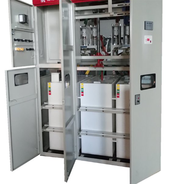
Touch Screen: 7–10 inch color screens (e.g., Weintek MT series) displaying real-time parameters (current, temperature, vibration), status, and fault codes, supporting manual operations (e.g., remote start/stop, parameter settings).
Control Cabinet: IP54-rated, housing all electrical components. Constructed from 1.5 mm cold-rolled steel with welded joints, surface electrostatically powder-coated (RAL 7035 light gray) for dust and moisture resistance.
II. Manufacturing and Assembly Process of the Electrical Control System
The manufacturing process centers on "component selection → cabinet fabrication → wiring/assembly → programming → debugging," with details as follows:
Component Selection and Cabinet Fabrication
Component Selection: Choose components based on crusher power (e.g., 55 kW, 110 kW) and operating conditions (dust, temperature). Contactors and breakers are derated (10%–20% lower rated current in high-temperature environments), and sensors have ≥IP65 protection.
Cabinet Fabrication: Cold-rolled steel undergoes laser cutting (tolerance ±0.5 mm), CNC bending (angle tolerance ±1°), and welding (slag removed and polished). It is then phosphated (5–10 μm film) and powder-coated (60–80 μm thickness, adhesion ≥5 N/cm).
Internal Wiring and Assembly
Wiring Design: Power circuits use copper bars (TMY-3×30×3 mm, current capacity ≥300 A) or multi-strand copper cables (10–50 mm² cross-section). Control circuits use 0.75–1.5 mm² shielded wires (to resist EMI), with strong and weak circuits separated by ≥100 mm.
Wiring Process: Wire ends are crimped with cold-pressed terminals (matched to wire size, crimped with hydraulic tools for ≥100 N pull force). UK series DIN rail terminals (5.08 mm pitch) are used, with secure connections (no loosening under vibration) and clear heat-shrinkable labels (≥105℃ resistance).
Component Installation: Breakers and contactors are mounted on DIN rails (levelness ≤1 mm/m). PLCs and HMIs are fixed to mounting plates (verticality ≤1 mm/m), with ground terminals reliably connected to the cabinet (ground resistance ≤4Ω).
Programming and Debugging
Pre-power checks: Use multimeters to test insulation resistance (≥10 MΩ for power circuits, ≥5 MΩ for control circuits) and verify correct wiring (no short circuits or misconnections).
No-load debugging: Simulate inputs (e.g., temperature/current signals via generators) to test alarm/shutdown logic and start/stop responsiveness.
Load debugging: Connect the crusher motor to test startup current (≤6× rated current, startup time ≤10 seconds), current stability (fluctuation ≤5%), and overload protection (contactor tripping during simulated overloads).
PLC Programming: Use ladder logic or SCL to write programs based on control logic (e.g., "Start condition: emergency stop not pressed + no faults + feeder ready"). Programs include main routines (operation control), subroutines (alarm handling), and interrupt routines (emergency shutdown), validated via syntax and logic checks.
HMI Design: Create pages for real-time parameters, settings, and fault logs (storing 100 entries with timestamps and codes) with user-friendly buttons and icons.
System Commissioning:
III. Quality Control Process of the Electrical Control System
Quality control covers "component inspection → assembly → final testing" to ensure reliability:
Incoming Component Inspection
Critical components (breakers, contactors) require certificates and test reports. Samples undergo switching tests (100 cycles without jamming) and insulation tests (2500 V AC for 1 minute, no breakdown).
Sensor calibration: Temperature sensors are calibrated in a thermostat (0℃, 50℃, 100℃; error ≤±0.5℃). Vibration transducers are calibrated on shakers (error ≤±0.05 mm/s).
In-Process Assembly Control
Wiring checks: Verify wire labels match drawings, terminal torque meets standards (1.5–2 N·m for M4 bolts), and shielded wires are grounded (resistance ≤1Ω).
Cabinet protection tests: IP54 validation via water spray (3 minutes, no internal water ingress) and dust tests (no significant dust accumulation on components).
Final Performance Testing
Functional Testing: Validate all logic (start/stop, alarms, protection) during 100-hour continuous operation (no crashes or false triggers).
EMC Testing: Anti-interference tests (1 kV pulse injection, no anomalies) and radiation emission tests (compliance with EN 61000-6-4 to avoid interfering with nearby equipment).
Temperature Cycling Testing: Operate in -10℃–50℃ chambers for 4 hours (no component failure or program errors).
Factory Acceptance
Provide technical documents (electrical schematics, wiring diagrams, manuals, component lists) and a "factory test report" (including insulation resistance, withstand voltage, and functional test data).
On-site support: Guide correct wiring (motor, sensor cables), debug until normal operation, and train operators (fault handling, maintenance).
IV. Routine Maintenance Tips
Clean the control cabinet quarterly (using compressed air to remove dust, preventing short circuits) and check terminal tightness (avoiding loose connections and overheating).
Calibrate sensors monthly (especially temperature and vibration sensors) to ensure accuracy.
Backup PLC programs and HMI configurations (preventing data loss) and log fault codes and solutions (building a maintenance database).
With strict manufacturing and quality control, the electrical control system achieves a mean time between failures (MTBF) of ≥5000 hours, ensuring stable operation of the jaw crusher