The cone crusher spring, a crucial safety and buffering component installed around the upper frame or between the adjustment ring and base, mainly functions in overload protection (absorbing impact energy to prevent damage from foreign objects), vibration damping (reducing noise and extending component life), providing reset force (restoring positions post-overload), and applying preload (maintaining stable operation). It requires high fatigue resistance, elastic limit, and corrosion resistance, operating under 50–80% of ultimate compressive strength preload.
Structurally, it is a helical compression spring consisting of a spring coil (high-carbon spring steel wire like 60Si2MnA, 20–80 mm diameter), end faces (ground flat for stability), spring diameter (OD 150–500 mm, ID, with 20–100 mm pitch), optional hooks/connections, and surface coating (zinc plating, epoxy, etc.). Its design features a spring rate of 50–200 kN/mm for large crushers.
The manufacturing process (wire forming, no casting) includes material selection and preparation (inspecting and straightening high-carbon spring steel wire), coiling (using CNC machines to control pitch, diameter, and coil number), heat treatment (quenching and tempering to achieve HRC 45–50 hardness), and end processing (grinding ends flat and deburring). For multi-spring systems, assembly involves selection/matching, mounting plate installation, and preload setting.
Quality control covers material testing (chemical composition and tensile strength), dimensional checks (CMM for coil parameters and spring rate testing), mechanical property testing (hardness and fatigue testing), non-destructive testing (MPT and UT for defects), and corrosion resistance testing (salt spray testing). These ensure the spring reliably protects against overload and dampens vibration, maintaining stable crusher operation in harsh environments
Detailed Introduction to the Cone Crusher Spring Component
1. Function and Role of the Spring
The cone crusher spring (also called the safety spring or compression spring) is a critical safety and buffering component installed around the upper frame or between the adjustment ring and base. Its primary functions include:
Overload Protection: Absorbing impact energy when foreign objects (e.g., metal scraps) enter the crushing chamber, compressing to allow temporary separation of the moving and fixed cones, preventing damage to the main shaft, gears, and liners.
Vibration Damping: Reducing high-frequency vibrations generated during crushing, minimizing noise and extending the service life of bearings and other precision components.
Reset Force: After overload, providing restoring force to return the adjustment ring or moving cone to its original position, ensuring the crushing gap is maintained.
Preload Application: Maintaining constant pressure on the adjustment ring to prevent loosening, ensuring stable operation under varying material loads.
Given its role in dynamic load absorption, the spring must 具备 high fatigue resistance, elastic limit, and corrosion resistance, typically operating under a preload of 50–80% of its ultimate compressive strength.
2. Composition and Structure of the Spring
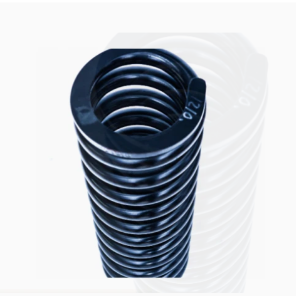
Cone crusher springs are usually helical compression springs with a robust design, consisting of the following key components and structural details:
Spring Coil: The main body, made of high-carbon spring steel wire (e.g., 60Si2MnA or 50CrVA) with a diameter ranging from 20 mm to 80 mm. The coil features a uniform helix structure with a specified number of active coils (typically 5–15) and end coils (1–2) for stable seating.
End Faces: The top and bottom coil ends, which may be ground flat (for parallel end springs) or squared (for non-ground ends), ensuring perpendicularity to the spring axis and uniform load distribution.
Spring Diameter: Including outer diameter (OD, 150–500 mm) and inner diameter (ID), with a pitch (distance between adjacent coils) of 20–100 mm to allow sufficient compression stroke (typically 10–30% of free length).
Hook or Connection Features (Optional): For smaller springs, end hooks may be formed to attach to the adjustment ring or base, though most large crusher springs use flat ends for direct contact.
Surface Coating: A protective layer such as zinc plating, epoxy coating, or oil immersion to resist corrosion, especially in humid or dusty mining environments.
The spring’s design is characterized by its spring rate (stiffness), calculated to provide the required force-displacement response—typically 50–200 kN/mm for large cone crushers.
3. Manufacturing Process for the Spring (Wire Forming, No Casting)
Unlike metal components, springs are not cast but manufactured via wire forming and heat treatment. The key steps are:
Material Selection and Preparation:
High-carbon spring steel wire (60Si2MnA) is chosen for its excellent elastic limit (≥1200 MPa) and fatigue strength. The wire is inspected for surface defects (scratches, cracks) and straightened to ensure uniform diameter (tolerance ±0.1 mm).
Coiling:
The wire is fed into a CNC spring coiling machine, which bends it into a helical shape using precision mandrels and rollers. The machine controls:
Pitch: Ensuring uniform spacing between coils (tolerance ±0.5 mm).
Diameter: Maintaining outer diameter within ±1 mm of the design value.
Number of Coils: Precisely counting active and end coils to meet the free length specification (tolerance ±2 mm).
Heat Treatment:
Quenching and Tempering: The coiled spring is heated to 850–880°C in a furnace, held for 30–60 minutes, then quenched in oil to achieve a martensitic structure. It is then tempered at 420–480°C for 1–2 hours to reduce brittleness, resulting in a hardness of HRC 45–50 and a tensile strength of 1600–1900 MPa.
This process sets the spring’s elastic properties, ensuring it can withstand repeated compression without permanent deformation.
End Processing:
End coils are ground flat using a surface grinder to achieve parallelism (≤0.1 mm/m) and perpendicularity to the spring axis (≤0.5°), ensuring stable seating on the upper frame and base.
Deburring removes sharp edges from the ground ends to prevent stress concentration and damage to mating surfaces.
4. Manufacturing Process for Spring Assemblies (Large Multi-Spring Systems)
Some crushers use multiple smaller springs arranged in a circular pattern; their assembly involves:
Spring Selection and Matching:
Springs are sorted by free length and spring rate (stiffness) to ensure uniform load distribution. Springs with a rate variation >5% are rejected to prevent uneven loading.
Mounting Plate Installation:
Upper and lower mounting plates (steel or cast iron) with holes matching the spring outer diameter are used to position the springs. Each spring is inserted into its hole and secured with retaining rings to prevent lateral movement.
Preload Setting:
The assembly is compressed to the specified preload (using a hydraulic press) and locked in place with shims, ensuring each spring bears equal load (measured via load cells with a tolerance ±2%).
5. Quality Control Processes
Material Testing:
Chemical composition analysis (spectrometry) confirms the spring steel meets standards (e.g., 60Si2MnA: C 0.56–0.64%, Si 1.50–2.00%, Mn 0.60–0.90%).
Tensile testing on wire samples measures ultimate tensile strength (≥1600 MPa) and elongation (≥6%).
Dimensional Accuracy Checks:
A coordinate measuring machine (CMM) inspects coil diameter, pitch, free length, and end flatness, ensuring compliance with design tolerances.
A spring tester measures the rate (force per mm compression) to verify it falls within the specified range (±5%).
Mechanical Property Testing:
Hardness testing (Rockwell) ensures the spring has a hardness of HRC 45–50; core hardness is checked via microhardness profiling to confirm uniform heat treatment.
Fatigue testing subjects the spring to 10⁶ compression cycles (from 10% to 70% of maximum deflection) with no cracks or permanent deformation allowed.
Non-Destructive Testing (NDT):
Magnetic particle testing (MPT) detects surface cracks in the coils, especially at coil bends (stress concentration points), with any crack >0.2 mm in length resulting in rejection.
Ultrasonic testing (UT) inspects the wire for internal defects (e.g., inclusions) that could reduce fatigue life.
Corrosion Resistance Testing:
Salt spray testing (ASTM B117) for 48 hours evaluates zinc-plated or painted springs, with no red rust allowed on critical surfaces.
Through these processes, the cone crusher spring achieves reliable overload protection and vibration damping, ensuring the crusher can handle unexpected foreign objects and maintain stable operation in harsh mining environments