This paper provides a detailed introduction to the locking nut component of cone crushers. As an important fastening component, it is mainly used to secure key assemblies such as the main shaft, fixed cone liner, or adjustment ring. It can realize functions including secure fixation, load distribution, and maintaining the crushing gap in cooperation with the adjustment ring.
Its composition and structure include the nut body, threaded bore, locking mechanism (such as locking holes, set screws, and tapered surfaces), flange or shoulder, and wrench flat faces, with each part having a specific design and function. In terms of casting process, large-sized locking nuts often use gray cast iron, ductile iron, or cast steel, going through steps such as material selection, pattern making, molding, melting and pouring, cooling and cleaning, and heat treatment.
The machining and manufacturing process covers steps like rough machining, machining of locking features, finish machining, surface treatment, and assembly with locking components. Quality control includes measures such as material testing, dimensional accuracy checks, thread quality inspection, locking performance testing, and non-destructive testing, ensuring that the component has good wear resistance, anti-loosening performance, and structural rigidity in high-vibration environments, thus guaranteeing the stable operation of the crusher.
Detailed Introduction to the Cone Crusher Locking Nut Component
1. Function and Role of the Locking Nut
The cone crusher locking nut (also known as the clamping nut or retaining nut) is a critical fastener component used to secure key assemblies such as the main shaft, fixed cone liner, or adjustment ring. Its primary functions include:
Secure Fixation: Locking the fixed cone liner to the main frame or securing the main shaft to the eccentric assembly, preventing loosening caused by high-frequency vibration during crushing.
Load Distribution: Evenly distributing axial and radial loads across the connected components, reducing localized stress and avoiding deformation.
Adjustment Compatibility: Working in conjunction with the adjustment ring to maintain the correct crushing gap by locking the adjusted position, ensuring stable discharge particle size.
Given its role in high-vibration environments, the locking nut must 具备 high wear resistance, anti-loosening performance, and structural rigidity.
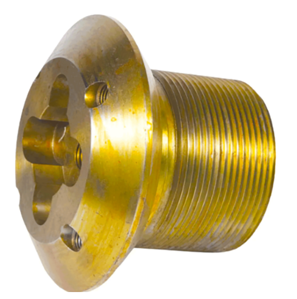
2. Composition and Structure of the Locking Nut
The locking nut is typically a large-sized, heavy-duty hexagonal or round nut with internal threads, featuring the following components and structural details:
Nut Body: A cylindrical or hexagonal main structure made of high-strength alloy steel (e.g., 45# steel or 40Cr),with internal threads (metric or inch) machined to precise tolerances (class 6H). The outer surface may be hexagonal for wrench tightening or round with holes for locking pins.
Threaded Bore: The central internal thread that mates with the corresponding external thread on the main shaft or adjustment ring. Threads are often coated with anti-seize compound to prevent galling during installation/removal.
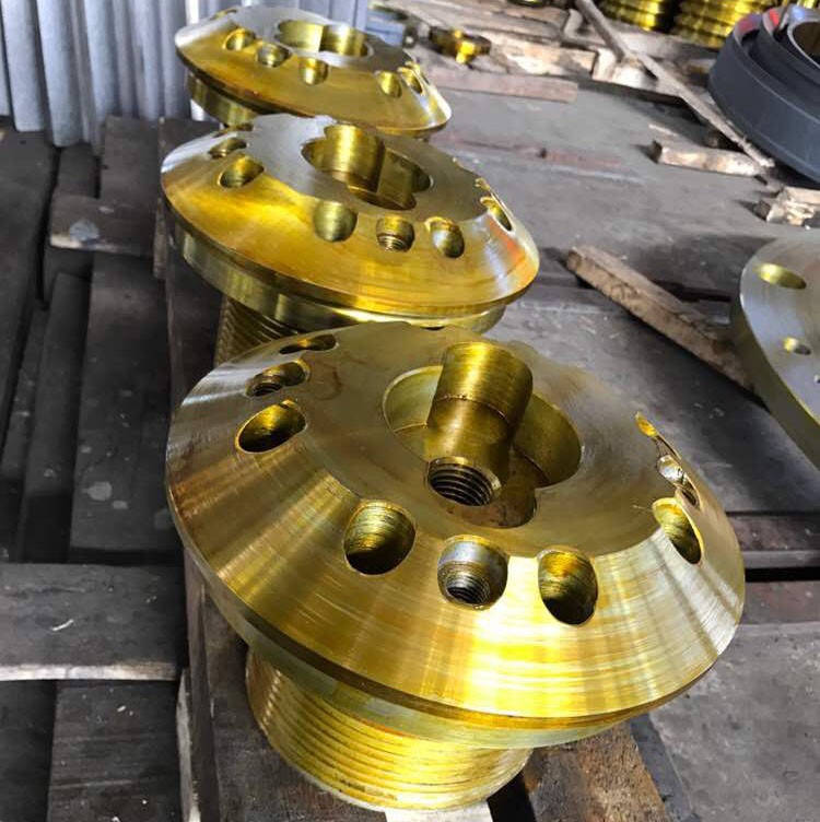
Locking Mechanism: Additional features to prevent loosening, such as:
Locking Holes: Radial holes drilled through the nut body to insert locking pins, which engage with slots on the mating component.
Set Screws: Threaded holes on the nut’s side to accommodate set screws that press against the mating surface, creating friction locking.
Tapered Surface: A conical seat on one end of the nut that mates with a corresponding taper on the fixed cone or adjustment ring, enhancing axial locking force.
Flange or Shoulder: A radial projection on one end of the nut that acts as a stop, limiting axial movement and ensuring proper seating against the connected component.
Wrench Flat Faces: Six flat surfaces on hexagonal nuts (or two parallel flats on round nuts) to allow torque application via a spanner or hydraulic torque wrench.
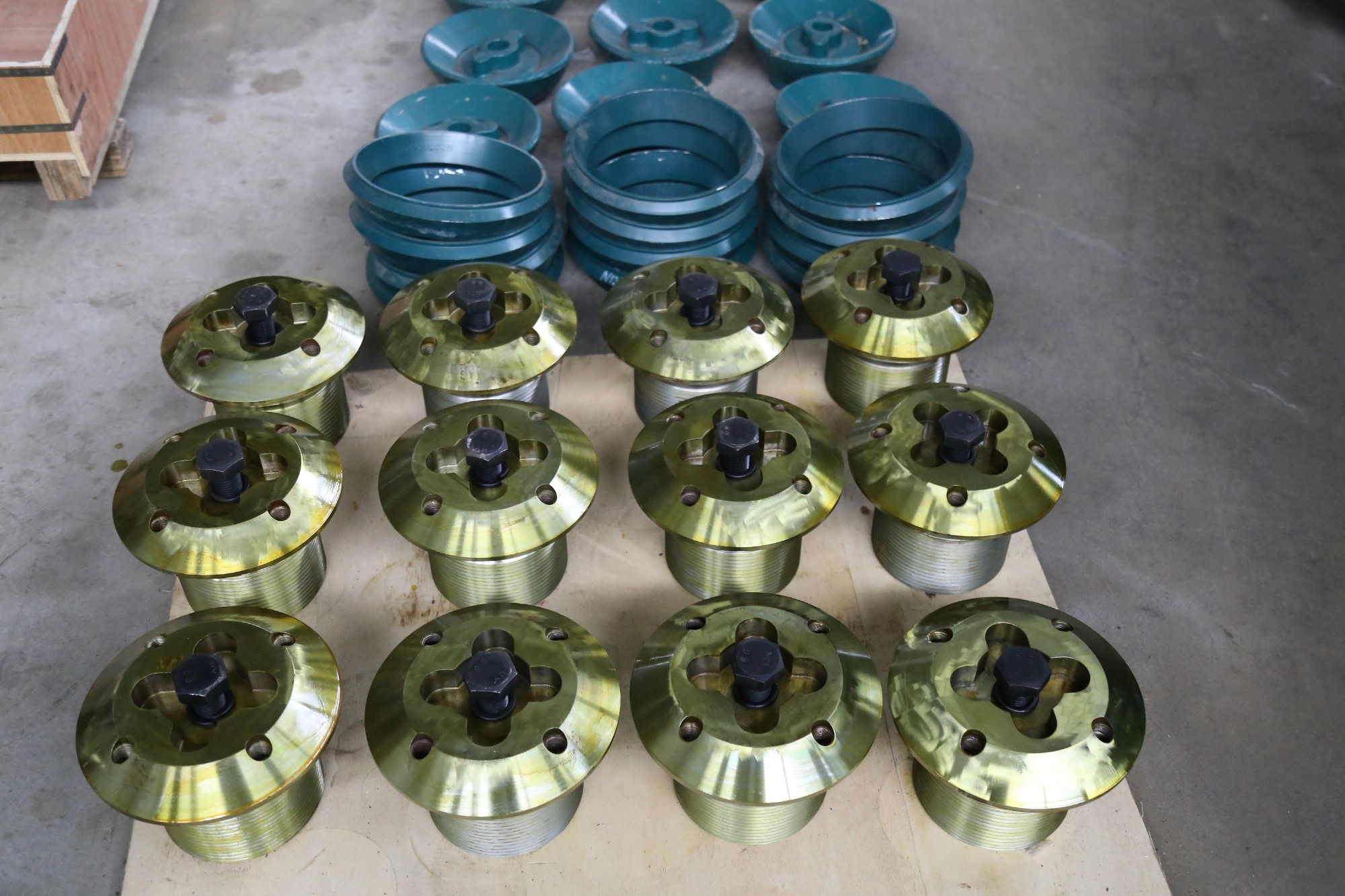
3. Casting Process for the Locking Nut
For large locking nuts (outer diameter >300 mm), casting is often used to form the rough shape, with the following steps:
Material Selection:
High-quality gray cast iron (HT300) or ductile iron (QT500-7) is chosen for its good castability and machinability. For high-load applications, cast steel (ZG310-570) is preferred for higher strength.
Pattern Making:
A wooden or foam pattern is created, replicating the nut’s outer shape, flange, and pre-drilled hole positions. Shrinkage allowances (1–1.5%) are added to account for cooling contraction.
Molding:
Sand molds are prepared using resin-bonded sand, with a core to form the internal threaded bore (left rough for post-casting machining). The mold cavity is coated with a refractory coating to improve surface finish.
Melting and Pouring:
For cast iron: Molten iron (1380–1420°C) is poured into the mold using a ladle, with controlled pouring speed to avoid turbulence and porosity.
For cast steel: Melted in an electric arc furnace (1500–1550°C) and poured into the mold, with stricter temperature control to ensure complete filling.
Cooling and Shakeout:
The casting is cooled in the mold for 24–48 hours to reduce thermal stress, then removed via vibration. Sand residues are cleaned using shot blasting.
Heat Treatment:
Cast iron nuts undergo annealing (550–600°C) to relieve casting stress and improve machinability.
Cast steel nuts are normalized (850–900°C, air-cooled) to refine grain structure, achieving a hardness of 180–220 HBW.
4. Machining and Manufacturing Process
Rough Machining:
The cast or forged blank is mounted on a CNC lathe to machine the outer diameter, flange face, and both end faces, leaving 1–2 mm finishing allowance.
The internal bore is rough-drilled and tapped to a pre-thread size, ensuring the thread root diameter is within tolerance.
Locking Feature Machining:
Locking holes or set screw holes are drilled using a CNC drilling machine, with positional tolerance (±0.1 mm) relative to the threads.
Tapered surfaces (if applicable) are turned using a CNC lathe, with angle tolerance (±0.5°) and surface roughness Ra3.2 μm.
Finish Machining:
The internal thread is precision-tapped to the final size (class 6H) using a thread tap with coolant, ensuring smooth thread flanks and correct pitch diameter.
The outer hexagonal surfaces (or round surface) are finish-turned to achieve dimensional tolerance (±0.1 mm) and surface roughness Ra1.6 μm.
End faces are ground to ensure flatness (≤0.05 mm/m) and perpendicularity to the thread axis (≤0.02 mm).
Surface Treatment:
The nut surface is coated with anti-rust paint or zinc plating (5–8 μm thickness) to prevent corrosion, especially for outdoor or humid environments.
Threads are coated with molybdenum disulfide-based anti-seize compound to facilitate future disassembly.
Assembly with Locking Components:
Locking pins or set screws are installed in their respective holes, with pins protruding 5–10 mm to engage with mating slots.
5. Quality Control Processes
Material Testing:
Chemical composition analysis (spectrometry) confirms the base material meets standards (e.g., 45# steel: C 0.42–0.50%, Mn 0.50–0.80%).
Hardness testing (Brinell) ensures cast iron nuts have hardness 180–230 HBW; steel nuts 200–250 HBW.
Dimensional Accuracy Checks:
Thread parameters (pitch diameter, major diameter, minor diameter) are inspected using thread gauges (ring gauges for internal threads) to ensure class 6H tolerance.
A coordinate measuring machine (CMM) verifies outer dimensions, hole positions, and taper angles, ensuring compliance with drawings.
Thread Quality Inspection:
Thread profile is checked using a thread comparator to ensure no burrs, cracks, or incomplete threads.
A thread fit test is performed by mating the nut with a gauge bolt, ensuring smooth engagement without excessive play or binding.
Locking Performance Testing:
For locking pin designs: The nut is installed on a test fixture, and the locking pin is inserted to verify engagement with the slot, ensuring no axial movement under 50% of the rated torque.
For set screw designs: Set screws are tightened to the specified torque, and the nut is subjected to vibration testing (10–500 Hz) for 1 hour, with no loosening allowed.
Non-Destructive Testing (NDT):
Magnetic particle testing (MPT) is performed on high-load nuts to detect surface cracks in the thread roots or locking holes.
Visual inspection checks for surface defects (scratches, dents) that could affect seating or torque application.
By adhering to these manufacturing and quality control processes, the cone crusher locking nut ensures reliable fixation of critical components, withstanding high vibration and load conditions to maintain crusher stability and safety