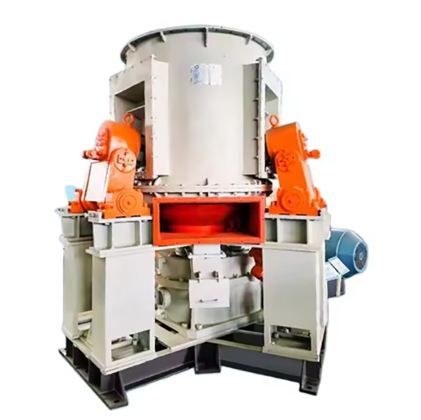
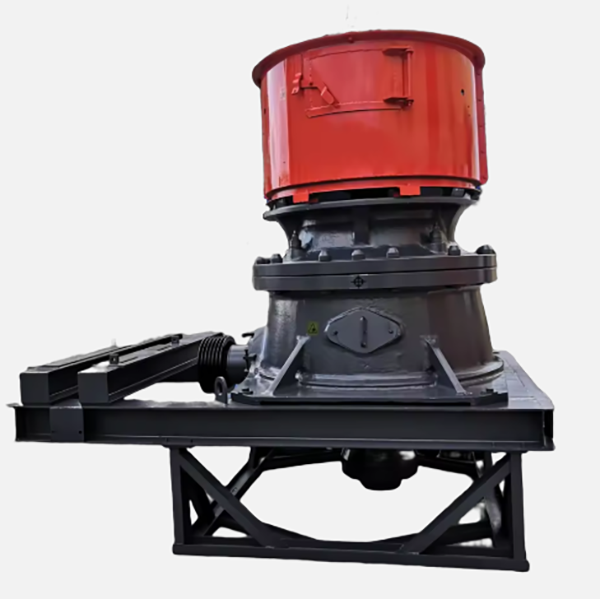
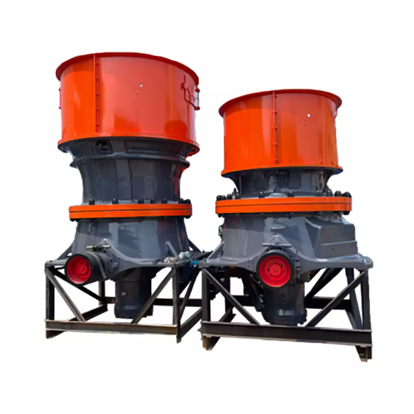
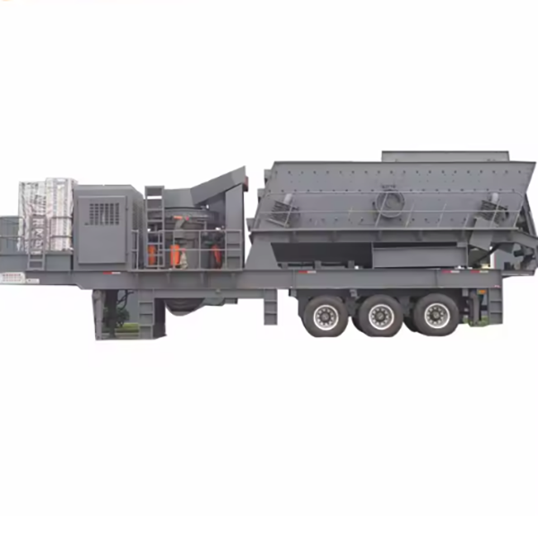
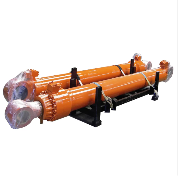
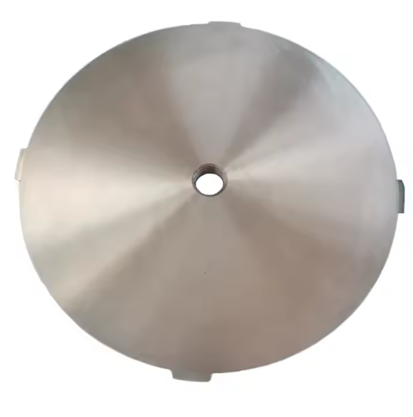
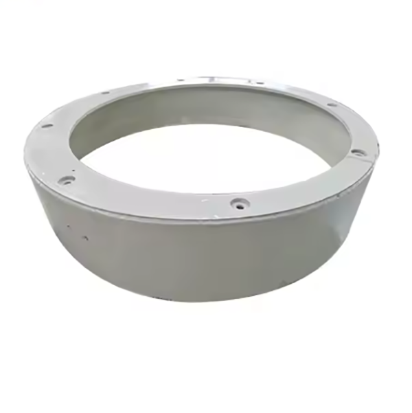
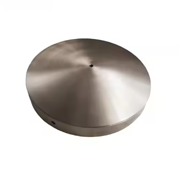
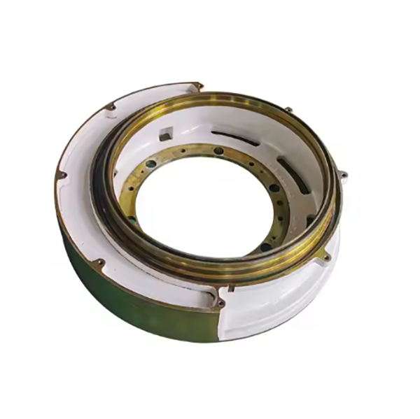
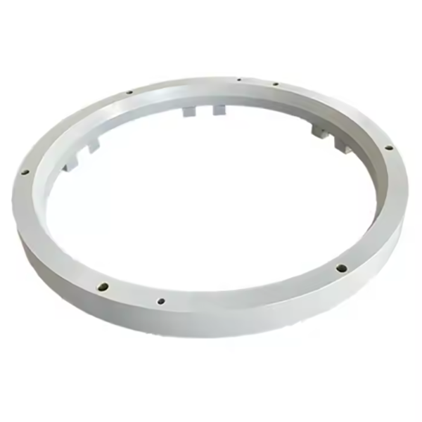
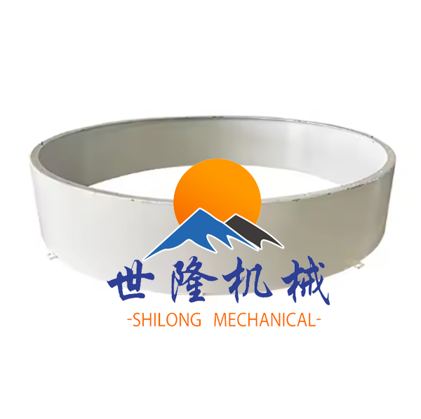
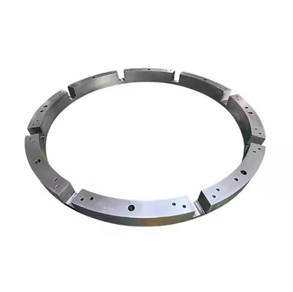
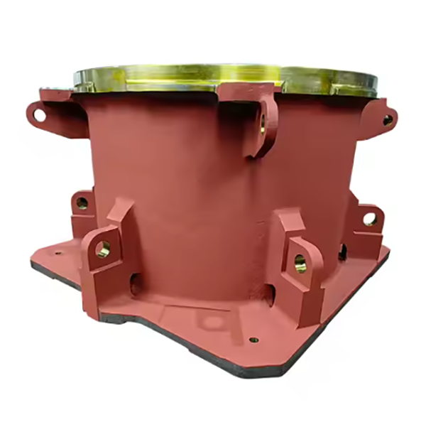
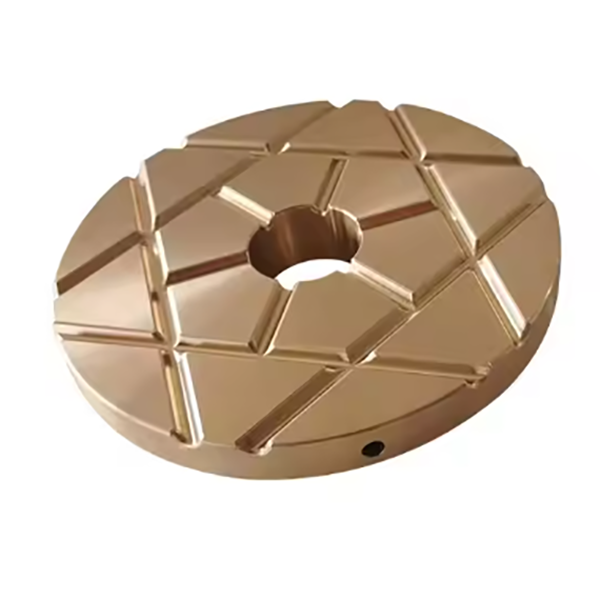
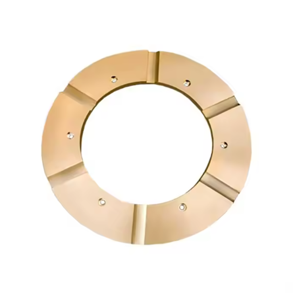
The safety cylinder (also known as the release cylinder) is a core safety component of cone crushers, primarily responsible for protecting the equipment from overload impacts. When uncrushable materials (such as iron blocks) enter the crusher or the material load exceeds the limit, the hydraulic oil in the safety cylinder is rapidly released through the relief valve, pushing the moving cone upward to increase the gap in the crushing chamber and allow foreign objects to be discharged. After the foreign objects are expelled, the hydraulic system resets, and the moving cone returns to its working position, ensuring continuous and stable operation of the equipment.
The safety cylinder is a hydraulically driven cylindrical component, consisting of the following core parts:
The cylinder body serves as the container for hydraulic oil and the piston, withstanding internal hydraulic pressure. It has a hollow cylindrical structure, and its inner wall requires high-precision machining to ensure sealing performance and smooth piston movement. Materials are typically high-strength cast iron or cast steel.
The piston transmits hydraulic power to drive the displacement of the moving cone. It is a cylindrical structure matching the inner wall of the cylinder body, with its top connected to the moving cone connecting rod. Its surface is usually subjected to wear-resistant treatment.
The sealing assembly prevents hydraulic oil leakage (both internal and external). It consists of O-rings, composite seals (such as Glyd rings, U-cup seals), and dust seals, installed at the piston and the end of the cylinder body.
The oil inlet/outlet connects to the hydraulic pipeline to realize the injection and discharge of hydraulic oil. Located on the side wall of the cylinder body, it features a threaded interface (e.g., British pipe thread) to match the hydraulic system.
The guide sleeve ensures the coaxiality of the piston movement and reduces eccentric wear. It is sleeved on the outside of the piston, made of wear-resistant cast iron or copper alloy, with an inner hole precision of IT7 grade.
Some models are equipped with a buffering device to reduce impact during rapid reset of the piston. Composed of a buffer sleeve and a throttle hole, it is located at the bottom of the cylinder body and achieves buffering through hydraulic oil throttling.
Core components such as the cylinder body and piston of the safety cylinder are mostly formed by casting processes, with the specific flow as follows:
Material Selection
Cylinder body: High-strength gray cast iron (HT300) or ductile iron (QT500-7) is selected, requiring a tensile strength ≥500MPa and hardness of 180-240HBW to ensure high-pressure resistance and deformation resistance.
Piston: Ductile iron (QT600-3) or cast steel (ZG35CrMo) is commonly used, requiring high wear resistance and toughness.
Mold Design and Manufacturing
Sand molds (resin sand or sodium silicate sand) are made according to part drawings, with a machining allowance of 3-5mm reserved. Reasonable risers and gates are designed to avoid shrinkage cavities and porosity. For cylinder body molds, the cylindricity of the inner cavity must be guaranteed to prevent post-casting ellipticity or bending.
Melting and Pouring
Cast iron melting: An intermediate frequency induction furnace is used, with the molten iron temperature controlled at 1450-1500℃. The chemical composition (e.g., carbon: 3.2-3.6%, silicon: 1.8-2.2%) is adjusted to ensure fluidity and mechanical properties.
Pouring: A bottom-pouring system is adopted, with the pouring speed controlled at 5-8kg/s to avoid slag entrainment. After pouring, the casting is slowly cooled in the furnace to below 200℃ to reduce internal stress.
Shakeout and Cleaning
After cooling to room temperature, the sand mold is removed by vibration shakeout. The risers and gates are cleaned by gas cutting or grinding, requiring residual height ≤1mm.
Heat Treatment
Cylinder body: Stress relief annealing is performed by heating to 550-600℃, holding for 2-3 hours, and slow cooling to 200℃ before 出炉 to eliminate casting stress and prevent post-machining deformation.
Piston: If made of cast steel, normalizing is conducted by heating to 850-900℃, holding for 1 hour, and air cooling to refine grains and improve toughness.
Casting Inspection
Visual inspection: Ensuring no cracks, shrinkage cavities, or sand holes.
Non-destructive testing: Ultrasonic testing (UT) is applied to critical areas (e.g., cylinder inner wall) with 100% coverage, prohibiting pores or inclusions ≥φ3mm.
Casting blanks require machining to meet design accuracy, with the specific process as follows:
Rough Machining
Cylinder body: Turning the outer circle, end face, and inner cavity, leaving a finishing allowance of 1-2mm; drilling and tapping oil inlet/outlet threads (e.g., G1/2).
Piston: Turning the outer circle and end face, machining grooves for seals (width and depth tolerance ±0.05mm).
Finish Machining
Cylinder inner wall: Honing to achieve a surface roughness of Ra0.8-1.6μm, cylindricity ≤0.01mm/m, and diameter tolerance of IT7 grade.
Piston outer circle: Precision grinding to Ra1.6μm, with the fit clearance with the cylinder inner wall controlled at 0.03-0.08mm (adjusted according to hydraulic oil viscosity).
Guide sleeve: Precision boring + honing of the inner hole to ensure fit accuracy with the piston.
Surface Treatment
Cylinder outer surface: Painting (primer + topcoat) or electroplating (zinc plating and passivation) for corrosion resistance; the inner cavity remains untreated (lubricated by hydraulic oil).
Piston surface: Hard chrome plating (thickness 0.05-0.1mm), followed by precision grinding to ensure dimensional accuracy and improve wear resistance.
Assembly
Installing the sealing assembly: Sequentially fitting dust seals, main seals (e.g., Glyd rings), and guide rings, ensuring no distortion or scratches.
Assembling piston and cylinder: Slowly pushing the piston to avoid damaging seals, and testing smooth movement (no jamming).
The quality of the safety cylinder directly affects the safety performance of the crusher, requiring strict control in the following links:
Raw Material Inspection
Chemical composition analysis: Using a spectrometer to detect elements such as carbon, silicon, and manganese in cast iron/cast steel, ensuring compliance with material standards.
Mechanical property testing: Sampling for tensile tests (measuring tensile strength and elongation) and hardness tests (Brinell hardness tester).
Machining Accuracy Inspection
Dimensional accuracy: Using internal and external micrometers to inspect cylinder inner diameter and piston outer diameter, with tolerances within IT7 grade.
Geometric tolerance: Using a roundness meter to check the roundness of the cylinder inner wall, and a dial indicator to test piston straightness (≤0.02mm/m).
Surface quality: Using a roughness meter to measure Ra values, with visual inspection ensuring no peeling or pinholes in the chrome plating.
Hydraulic Performance Testing
Seal test: Holding pressure at rated working pressure (usually 10-20MPa) for 30 minutes, with leakage ≤0.1mL/min.
Operation test: Simulating overload conditions, injecting hydraulic oil, observing smooth piston lifting/lowering, and reset accuracy error ≤0.5mm.
Fatigue Life Testing
Sampling for over 100,000 reciprocating cycles, inspecting seal wear after testing, and detecting cylinder cracks via magnetic particle testing.
Factory Inspection
Each safety cylinder must be accompanied by an inspection report containing dimensional and performance test data, with unqualified products prohibited from leaving the factory.
The safety cylinder is the "safety barrier" of cone crushers. Its structural design must balance strength and sealing performance, with casting and machining processes ensuring high precision and wear resistance. Quality control covers the entire process from raw materials to processing and assembly. A reasonable process scheme ensures the safety cylinder responds quickly to overloads, extending the service life of the crusher

