This paper elaborates on the Cone Crusher Hopper component, a crucial material guiding part located at the top of the crusher. Its main functions include material collection and storage, uniform distribution, impact buffering, and contamination prevention, requiring high wear resistance, structural strength, and corrosion resistance.
The hopper is typically funnel-shaped or rectangular, composed of the hopper body, feed grate/screen, wear liners, reinforcing ribs, mounting flange, access door, and optional vibration device mounts, each with specific structural features and roles.
For cast steel variants, the casting process involves material selection (high-strength cast steel like ZG270–500), pattern making, molding, melting and pouring, cooling and shakeout, heat treatment, and casting inspection. Most hoppers, however, are fabricated from steel plates through plate cutting, forming and bending, welding assembly, post-weld treatment, machining of mounting features, liner installation, and surface treatment.
Quality control processes cover material validation, dimensional accuracy checks, weld quality inspection, structural integrity testing, liner performance testing, and final inspection. These ensure the hopper can withstand abrasive wear and impact, guaranteeing continuous and efficient operation of the cone crusher in relevant applications.
Detailed Introduction to the Cone Crusher Hopper Component
1. Function and Role of the Hopper
The cone crusher hopper (also called the feed hopper or inlet hopper) is a critical material guiding component located at the top of the crusher, serving as the entry point for raw materials. Its primary functions include:
Material Collection and Storage: Temporarily holding bulk materials (ores, rocks) before they enter the crushing chamber, ensuring a continuous feed supply.
Uniform Distribution: Guiding materials evenly into the crushing chamber to prevent uneven wear on the moving cone and fixed cone liners, optimizing crushing efficiency.
Impact Buffering: Reducing the impact force of falling materials (especially large chunks) through its inclined structure, protecting the crusher’s internal components from direct damage.
Contamination Prevention: Equipped with grates or screens to filter out oversized debris or foreign objects (e.g., metal scraps), avoiding jamming or damage to the crushing mechanism.
Given its role in handling abrasive and high-impact materials, the hopper must 具备 high wear resistance, structural strength, and corrosion resistance.
2. Composition and Structure of the Hopper
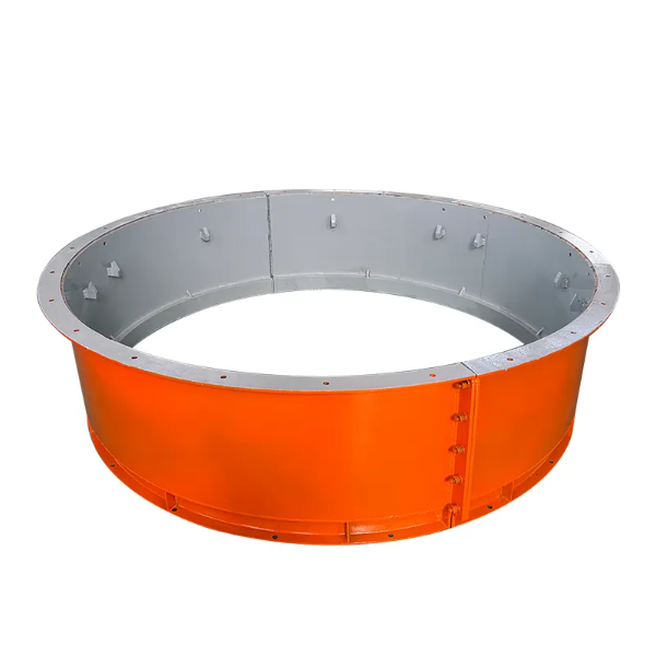
The hopper is typically a funnel-shaped or rectangular structure, composed of the following key parts and structural features:
Hopper Body: The main framework, usually made of thick steel plates (10–30 mm) or cast steel, with a tapered or curved cross-section to facilitate material flow. Its shape is designed to minimize material retention, with an outlet diameter matching the crushing chamber inlet (ranging from 300 mm to 1500 mm depending on the crusher model).
Feed Grate/Screen: A grid or perforated plate installed at the top inlet, with openings sized to control the maximum material size entering the crusher (typically 80–90% of the crushing chamber’s feed opening). Grates are removable for cleaning or replacement.
Wear Liners: Replaceable protective plates attached to the inner surface of the hopper body, made of high-chromium cast iron, abrasion-resistant steel (AR400/AR500), or rubber. These liners reduce direct wear on the hopper body and extend its service life.
Reinforcing Ribs: Steel ribs welded to the outer surface of the hopper body, enhancing structural rigidity to withstand material impact and prevent deformation. Ribs are arranged in a grid pattern or along the hopper’s taper.
Mounting Flange: A peripheral flange at the bottom of the hopper, featuring bolt holes for secure attachment to the crusher frame. The flange ensures alignment with the crushing chamber inlet and prevents material leakage.
Access Door: A hinged or removable door on the hopper side, allowing inspection, cleaning, or removal of blocked materials without disassembling the entire component.
Vibration Device Mounts (Optional): Brackets for attaching vibrators to prevent material bridging (blockage) in the hopper, especially when handling moist or sticky materials.
3. Casting Process for the Hopper (for Cast Steel Variants)
Large or complex-shaped hoppers (e.g., those with irregular tapers) are often manufactured via casting, with the following steps:
Material Selection:
High-strength cast steel (ZG270–500 or ZG310–570) is chosen for its excellent impact resistance (elongation ≥15%) and weldability, suitable for withstanding heavy material impact.
Pattern Making:
A full-scale foam or wood pattern is created, replicating the hopper’s taper, flange, and internal features. Shrinkage allowances (1.5–2%) are added to account for cooling contraction, and draft angles (3–5°) are included to facilitate pattern removal from the mold.
Molding:
Resin-bonded sand molds are formed around the pattern, with sand cores used to create internal cavities or reinforce thick sections. The mold surface is coated with a refractory wash (alumina-based) to improve surface finish and prevent metal penetration.
Melting and Pouring:
The cast steel is melted in an electric arc furnace at 1520–1560°C, with chemical composition controlled to C 0.25–0.35%, Si 0.2–0.6%, and Mn 0.6–1.0% to ensure strength and toughness.
Pouring is performed at 1480–1520°C using a ladle with a pouring basin to control flow rate, ensuring complete mold filling without turbulence (which can cause porosity).
Cooling and Shakeout:
The casting is cooled in the mold for 48–72 hours to reduce thermal stress, then removed via vibration. Sand residues are cleaned using shot blasting (G25 steel grit) to achieve a surface roughness of Ra25–50 μm.
Heat Treatment:
Normalization (850–900°C, air-cooled) refines the grain structure, followed by tempering (600–650°C) to reduce hardness to 180–220 HBW, improving machinability and toughness.
Casting Inspection:
Visual inspection and dye penetrant testing (DPT) check for surface cracks, blowholes, or cold shuts.
Ultrasonic testing (UT) inspects thick sections (≥20 mm) for internal defects, with any porosity >φ3 mm resulting in rejection.
4. Machining and Manufacturing Process (for Steel Plate Fabrication)
Most hoppers are fabricated from steel plates for cost-effectiveness and flexibility, with the following steps:
Plate Cutting:
Abrasion-resistant steel plates (AR400, 10–30 mm thick) are cut into flat sections using plasma cutting or laser cutting, with dimensional tolerances of ±1 mm. The hopper’s tapered sides are cut to precise angles using CNC cutting machines.
Forming and Bending:
Curved sections (if applicable) are formed using a hydraulic press with custom dies, ensuring consistent curvature (tolerance ±0.5°). Tapered sides are bent to the required angle (typically 45–60° from vertical) to facilitate material flow.
Welding Assembly:
The cut and formed plates are assembled into the hopper shape using submerged arc welding (SAW) for long seams and metal inert gas (MIG) welding for corners. Weld seams are ground smooth to avoid stress concentration, with a reinforcement height of 2–3 mm above the plate surface.
Reinforcing ribs are welded to the outer surface using fillet welds (leg length = plate thickness), with intermittent welds (100 mm welds spaced 150 mm apart) used on non-critical areas to reduce heat input.
Post-Weld Treatment:
Post-weld heat treatment (PWHT) is performed at 600–650°C for 2–4 hours to relieve welding stress, preventing cracking during operation. The hopper is then air-cooled to room temperature.
Machining of Mounting Features:
The mounting flange is machined on a CNC milling machine to ensure flatness (≤1 mm/m) and perpendicularity to the hopper axis (≤0.5 mm/m). Bolt holes are drilled using a CNC drilling machine, with positional tolerance ±0.5 mm.
Liner Installation:
Wear liners (high-chromium cast iron or AR500) are attached to the inner surface using countersunk bolts (M16–M24) spaced 200–300 mm apart. Rubber liners are bonded using epoxy adhesive, with mechanical fasteners added at edges for reinforcement.
Surface Treatment:
The outer surface is painted with anti-corrosion paint (epoxy primer + polyurethane topcoat, total thickness 80–120 μm) to protect against environmental corrosion. Welded areas are ground and primed before painting.
5. Quality Control Processes
Material Validation:
For cast hoppers: Spectrometric analysis confirms chemical composition (e.g., ZG310–570: C ≤0.37%, Mn ≤1.2%). Tensile testing on coupons verifies yield strength (≥310 MPa) and impact toughness (≥30 J/cm² at -20°C).
For fabricated hoppers: Ultrasonic testing (UT) of steel plates ensures no internal defects (e.g., laminations) in the base material.
Dimensional Accuracy Checks:
The hopper’s taper angle is measured using a protractor or laser scanner, with tolerance ±0.5°.
A coordinate measuring machine (CMM) verifies flange flatness, bolt hole positions, and outlet diameter (tolerance ±2 mm).
Weld Quality Inspection:
Weld seams are inspected via visual examination (no cracks, undercut ≤0.5 mm) and ultrasonic testing (UT) to detect internal defects (e.g., lack of fusion).
Destructive testing of weld samples (tensile and bend tests) confirms weld strength matches the base material (≥400 MPa).
Structural Integrity Testing:
Load testing: The hopper is mounted on a test rig and filled with weighted materials (120% of rated capacity) for 24 hours, with no visible deformation (measured via dial indicators) allowed.
Impact testing: A 50 kg steel block is dropped from 1 m onto the inner surface (wear liner removed) to simulate material impact, with post-test inspection showing no cracks or permanent deformation.
Liner Performance Testing:
Wear resistance of liners is evaluated using ASTM G65 dry sand/rubber wheel testing, with AR400 liners requiring weight loss ≤0.8 g/1000 cycles.
Liner adhesion (for bonded liners) is tested via a pull-off test, with minimum adhesion strength of 5 MPa required.
Final Inspection:
A comprehensive check ensures all components (grates, access door, mounting holes) meet design specifications.
The hopper is pressure-tested with air (0.1 MPa) to detect material leakage points around welds or flange connections.
By following these manufacturing and quality control processes, the cone crusher hopper achieves reliable material handling performance, withstanding abrasive wear and impact to ensure continuous, efficient operation of the crusher in mining, quarrying, and aggregate processing applications