This paper elaborates on the cone crusher feed plate, a key component in the material feeding system located at the top of the crusher's feed inlet. It functions to guide material flow, prevent backspray, reduce impact stress, and control feed rate. The component's composition and structure are detailed, including the plate body, mounting flange or bolt holes, impact-resistant liner, baffle plates (in some designs), reinforcing ribs, and chute or inclined surface, along with their structural features. For high-chromium cast iron variants, the casting process is described, covering material selection, pattern making, molding, melting, pouring, cooling and shakeout, heat treatment, and inspection. For steel plate variants, the machining and manufacturing process is outlined, including plate cutting, bending and forming, welding of reinforcements, surface treatment, and liner installation. Additionally, quality control measures are specified, such as material validation, dimensional accuracy checks, weld quality inspection, impact and wear testing, assembly and function testing, and final inspection. These processes ensure the feed plate has high impact resistance, wear resistance, and dimensional accuracy, guaranteeing reliable material feeding and protection for the cone crusher in heavy-duty operations.
Detailed Introduction to the Cone Crusher Feed Plate Component
1. Function and Role of the Feed Plate
The feed plate (also known as the feed hopper plate or inlet plate) is a key component in the material feeding system of cone crushers, located at the top of the crusher’s feed inlet. Its primary functions include:
Guiding Material Flow: Directing bulk materials (ores, rocks) uniformly into the crushing chamber, ensuring even distribution to avoid uneven wear on the moving cone and fixed cone liners.
Preventing Backspray: Acting as a barrier to block crushed material from splashing back out of the feed inlet during high-speed crushing, protecting operators and surrounding equipment.
Reducing Impact Stress: Absorbing initial impact forces when materials fall into the crusher, minimizing direct impact on the main shaft and eccentric assembly to extend their service life.
Controlling Feed Rate: Some feed plates are designed with adjustable baffles or channels to regulate the material flow rate, matching the crusher’s processing capacity and optimizing crushing efficiency.
2. Composition and Structure of the Feed Plate
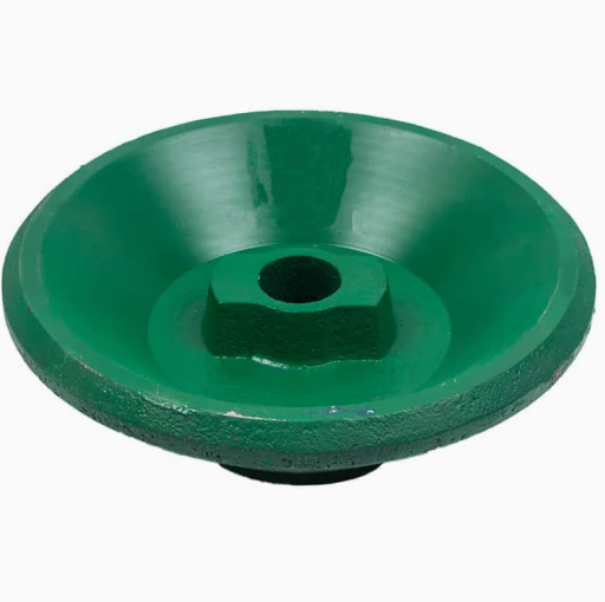
The feed plate is typically a heavy-duty, plate-like or funnel-shaped component, consisting of the following core parts:
Plate Body: The main structural component, made of high-strength abrasion-resistant steel (e.g., Mn13, AR400) or high-chromium cast iron (Cr20), with a thickness ranging from 30 to 100 mm depending on the crusher size. Its shape is tailored to the feed inlet, often featuring a curved or inclined surface to guide material flow.
Mounting Flange or Bolt Holes: A peripheral flange or array of bolt holes (M16–M24) on the plate body, used to secure it to the crusher frame or feed hopper. The flange is reinforced with rib plates to enhance structural rigidity under impact loads.
Impact-Resistant Liner: A replaceable wear layer attached to the inner surface of the plate body, made of ultra-high molecular weight polyethylene (UHMWPE) or ceramic tiles, which reduces friction and wear from abrasive materials.
Baffle Plates (in some designs): Adjustable or fixed vertical plates welded or bolted to the plate body, dividing the feed inlet into channels to control material direction and prevent bridging (material blockage).
Reinforcing Ribs: Triangular or rectangular steel ribs welded to the back of the plate body, improving its bending resistance and preventing deformation under repeated material impact.
Chute or Inclined Surface: A smooth, downward-sloping surface on the plate body (angle 30°–45°) to facilitate material sliding into the crushing chamber, with a polished finish to reduce material adhesion.
3. Casting Process for the Feed Plate (for High-Chromium Cast Iron Variants)
For feed plates made of high-chromium cast iron (used in heavy-abrasion applications), the casting process is as follows:
Material Selection:
High-chromium cast iron (Cr20–Cr26) with carbon content 2.5–3.5% is chosen for its high hardness (HRC 58–65) and abrasion resistance. Alloying elements such as Mo (0.5–1.0%) and Ni (0.5–1.5%) are added to improve toughness.
Pattern Making:
A full-scale pattern is created using wood or foam, replicating the plate body’s shape, flange, and bolt holes. Shrinkage allowances (1.5–2.0%) are added to compensate for post-casting contraction.
Molding:
Resin-bonded sand molds are prepared, with a sand core used to form bolt holes and internal channels. The mold cavity is coated with a refractory wash to prevent metal penetration and ensure a smooth surface.
Melting and Pouring:
The iron alloy is melted in an induction furnace at 1450–1500°C, with strict control of chromium and carbon content to avoid carbide segregation.
Pouring is performed at a temperature of 1380–1420°C, with a steady flow rate to ensure complete mold filling and minimize turbulence-induced porosity.
Cooling and Shakeout:
The casting is cooled in the mold for 24–48 hours to reduce thermal stress, then removed via vibration. Sand residues are cleaned using shot blasting.
Heat Treatment:
The casting undergoes quenching (950–1000°C, water-cooled) to form hard chromium carbides, followed by tempering (200–250°C) to relieve residual stress. This process achieves a hardness of HRC 58–65.
Casting Inspection:
Visual inspection and dye penetrant testing (DPT) check for surface cracks, blowholes, or incomplete filling.
Ultrasonic testing (UT) detects internal defects, with acceptable limits of ≤φ3 mm for non-critical areas and no defects in impact zones.
4. Machining and Manufacturing Process (for Steel Plate Variants)
For feed plates made of abrasion-resistant steel (AR400 or Mn13), the process focuses on cutting and welding rather than casting:
Plate Cutting:
Large steel plates are cut to the required shape using plasma cutting or laser cutting, with a tolerance of ±1 mm for dimensions. Bolt holes are drilled using CNC drilling machines, with countersinks added for flush bolt heads.
Bending and Forming:
The cut plate is bent into a curved or funnel shape using a hydraulic press, with forming dies ensuring consistent curvature (tolerance ±0.5°).
Welding of Reinforcements:
Reinforcing ribs and mounting flanges are welded to the plate body using submerged arc welding (SAW) or metal inert gas (MIG) welding. Weld seams are ground smooth to avoid stress concentration.
Post-weld heat treatment (PWHT) is performed at 600–650°C for 2–4 hours to reduce welding stress, preventing cracking during operation.
Surface Treatment:
The wear surface is polished to a roughness of Ra6.3–12.5 μm to minimize material adhesion. For AR400 plates, no additional coating is needed due to inherent wear resistance; Mn13 plates may be passivated to prevent rust.
Liner Installation:
Impact-resistant liners (UHMWPE or ceramic) are bonded to the inner surface using epoxy adhesives, with bolts added for reinforcement in high-wear areas. Liner edges are sealed with silicone to prevent material ingress between the liner and plate body.
5. Quality Control Processes
Material Validation:
For cast iron plates: Spectrometric analysis confirms chemical composition (Cr: 20–26%, C: 2.5–3.5%). Hardness testing (Rockwell C) ensures HRC 58–65.
For steel plates: Tensile testing verifies AR400’s strength (≥1300 MPa) and Mn13’s toughness (elongation ≥40%).
Curvature radius is measured using a template, with tolerance ±1 mm.
Weld Quality Inspection:
Weld seams are inspected via visual examination and ultrasonic testing (UT) to detect porosity, cracks, or incomplete fusion. Weld strength is tested via destructive sampling (tensile strength ≥480 MPa).
Impact and Wear Testing:
Impact testing: A 50 kg steel block is dropped from 1 m onto the plate surface, with no visible deformation or cracking allowed.
Abrasion testing: Samples undergo ASTM G65 dry sand/rubber wheel testing, with weight loss ≤0.5 g/1000 cycles for AR400 and ≤0.3 g/1000 cycles for high-chromium cast iron.
Assembly and Function Testing:
The feed plate is trial-mounted on the crusher frame to ensure proper alignment with the feed inlet (gap ≤2 mm).
A material flow test is conducted with simulated ore (50–100 mm particles) to verify uniform distribution and no backspray.
Final Inspection:
A comprehensive review of all test data, including material certificates, dimensional reports, and NDT results, is conducted before approval.
The plate is marked with part numbers, material grade, and inspection date for traceability.
Through these manufacturing and quality control measures, the feed plate achieves high impact resistance, wear resistance, and dimensional accuracy, ensuring reliable material feeding and protection for the cone crusher in continuous, heavy-duty operations