The cone crusher main shaft nut, a critical fastener at the top or bottom of the main shaft, secures components like the main shaft bearing, eccentric bushing, and moving cone. Its primary functions include axial fixation (preventing displacement from vibration and loads), load transfer (distributing axial loads up to hundreds of kilonewtons), bearing preload adjustment, and contamination prevention.
Structurally, it is a large heavy-duty fastener with a cylindrical or hexagonal profile, consisting of the nut body (high-strength alloy steel 42CrMo/35CrMo or cast steel ZG35CrMo), internal threads (class 6H tolerance, M30–M100 coarse-pitch), locking mechanisms (locking slots, tapered interface, set screw holes), torque application surface, seal groove, and shoulder/flange.
For large nuts (outer diameter >300 mm), the casting process involves material selection (ZG35CrMo), pattern making (with shrinkage allowances), molding (green sand or resin-bonded sand), melting and pouring (controlled temperature and flow), cooling and shakeout, and heat treatment (normalization and tempering). The machining process includes rough machining, thread machining, locking feature machining, heat treatment for hardening (induction-hardened threads to HRC 45–50), finish machining, and surface treatment.
Quality control covers material testing (chemical composition and hardness), dimensional checks (CMM and thread gauges), structural integrity testing (MPT and UT), functional testing (torque and vibration tests), and seal performance testing. These ensure the main shaft nut provides reliable fixation, enabling stable cone crusher operation under heavy loads and high vibrations
Detailed Introduction to the Cone Crusher Main Shaft Nut Component
1. Function and Role of the Main Shaft Nut
The cone crusher main shaft nut (also known as the spindle nut or shaft retaining nut) is a critical fastener located at the top or bottom end of the main shaft, serving to secure key components such as the main shaft bearing, eccentric bushing, or moving cone. Its primary functions include:
Axial Fixation: Locking the main shaft to the eccentric bushing or bearing housing, preventing axial displacement caused by high-frequency vibration and alternating loads during crushing.
Load Transfer: Distributing axial loads (up to hundreds of kilonewtons) from the moving cone and main shaft to the bearing system, ensuring balanced force transmission.
Bearing Preload Adjustment: Working with shims or washers to set the optimal preload for the main shaft bearing, reducing play and improving rotational stability.
Contamination Prevention: Creating a seal with the main shaft and adjacent components to block dust, ore particles, and moisture from entering the bearing system, extending service life.
Given its role in high-load, high-vibration environments, the main shaft nut must 具备 high tensile strength, impact resistance, and anti-loosening performance.
2. Composition and Structure of the Main Shaft Nut
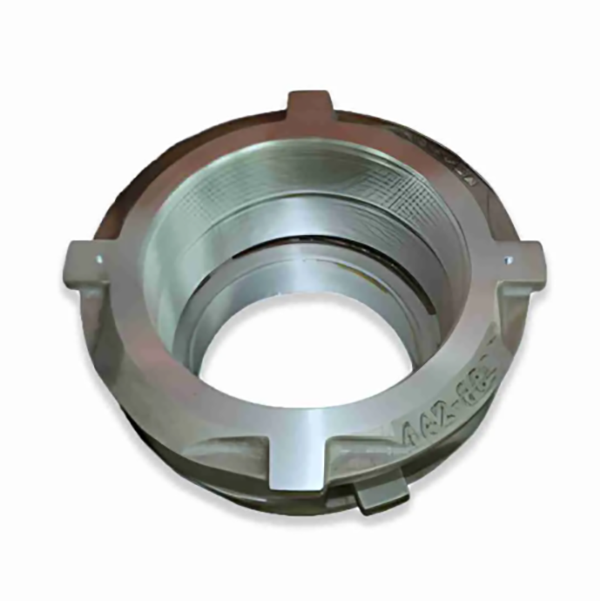
The main shaft nut is a large, heavy-duty fastener with a cylindrical or hexagonal profile, featuring the following key components and structural details:
Nut Body: The main structural section, typically made of high-strength alloy steel (e.g., 42CrMo or 35CrMo) with a solid or hollow design. Its outer diameter ranges from 150 mm to 600 mm, with a wall thickness of 20–50 mm depending on the crusher model.
Internal Threads: Precision-machined threads (metric or inch) that mate with the external threads of the main shaft. Threads are often coarse-pitch (M30–M100) to handle high axial loads, with a class 6H tolerance for tight fit.
Locking Mechanism: Features to prevent loosening under vibration, such as:
Locking Slots: Circumferential grooves on the nut’s outer surface that align with locking bolts on the eccentric bushing, restricting rotation.
Tapered Interface: A conical seat on one end that mates with a corresponding taper on the main shaft or bearing, enhancing grip under load.
Set Screw Holes: Radial threaded holes for set screws that press against the main shaft, creating friction-based locking.
Torque Application Surface: A hexagonal outer profile or square drive on the top face, allowing torque to be applied via a wrench or hydraulic tool during installation and removal.
Seal Groove: A circumferential groove on the inner or outer surface that houses an O-ring or gasket, improving sealing with adjacent components.
Shoulder or Flange: A radial projection on one end that acts as a stop, limiting the nut’s insertion depth and ensuring proper positioning relative to the bearing.
3. Casting Process for the Main Shaft Nut
For large-sized main shaft nuts (outer diameter >300 mm), casting is an efficient manufacturing method to achieve complex shapes:
Material Selection:
High-strength cast steel (ZG35CrMo) is preferred for its excellent mechanical properties: tensile strength ≥700 MPa, yield strength ≥500 MPa, and impact toughness ≥35 J/cm². It offers good machinability and hardenability, suitable for load-bearing applications.
Pattern Making:
A precision pattern is created using wood, foam, or 3D-printed resin, replicating the nut’s outer diameter, internal threads (simplified), locking features, and flange. Shrinkage allowances (1.5–2%) are added, with larger allowances for thick-walled sections.
The pattern includes a core to form the internal bore, ensuring dimensional accuracy of the thread root diameter.
Molding:
A green sand or resin-bonded sand mold is prepared, with the pattern positioned to form the outer shape and core for the inner bore. The mold cavity is coated with a refractory wash to improve surface finish and prevent sand inclusion.
Melting and Pouring:
The cast steel is melted in an electric arc furnace at 1520–1560°C, with chemical composition controlled to C 0.32–0.40%, Cr 0.8–1.1%, and Mo 0.15–0.25% to balance strength and toughness.
Pouring is performed at 1480–1520°C using a ladle, with a steady flow rate to avoid turbulence and ensure complete filling of the mold, especially in intricate locking features.
Cooling and Shakeout:
The casting is cooled in the mold for 48–72 hours to reduce thermal stress, then removed via vibration. Sand residues are cleaned using shot blasting (G25 steel grit), achieving a surface roughness of Ra25–50 μm.
Heat Treatment:
Normalization (850–900°C, air-cooled) refines the grain structure, followed by tempering (600–650°C) to reduce hardness to 180–230 HBW, improving machinability.
4. Machining and Manufacturing Process
Rough Machining:
The cast blank is mounted on a CNC lathe to machine the outer diameter, flange face, and top/bottom surfaces, leaving 2–3 mm finishing allowance. Key dimensions (e.g., nut height, flange thickness) are controlled to ±0.2 mm.
Thread Machining:
The internal threads are rough-cut using a thread tap or CNC thread milling machine, ensuring the pitch diameter is within 0.5 mm of the final size. For large nuts, a single-point threading tool is used to create the thread profile.
Locking Feature Machining:
Locking slots are milled into the outer surface using a CNC milling machine, with depth tolerance (±0.1 mm) and uniform spacing (±0.5 mm) around the nut’s circumference.
Set screw holes are drilled and tapped to class 6H tolerance, with perpendicularity (±0.1 mm/100 mm) relative to the nut’s axis to ensure proper engagement with the main shaft.
Heat Treatment for Hardening:
The nut’s thread surfaces and load-bearing areas are induction-hardened to a depth of 1–3 mm, achieving a surface hardness of HRC 45–50 to enhance wear resistance and thread strength.
Tempering at 200–250°C relieves residual stress, preventing cracking during finish machining.
Finish Machining:
The internal threads are finish-machined to class 6H tolerance using a precision thread tap or grinder, ensuring smooth thread flanks and correct pitch diameter for proper mating with the main shaft.
The tapered interface (if applicable) is ground to an angle tolerance (±0.1°) and surface roughness Ra1.6 μm, ensuring a tight seal with the main shaft.
The torque application surface (hexagonal profile) is finish-machined to achieve flatness (≤0.05 mm/m) and dimensional tolerance (±0.1 mm) for secure wrench engagement.
Surface Treatment:
The nut’s outer surface is coated with anti-rust paint or zinc plating (5–8 μm thick) to resist corrosion. Threads are treated with molybdenum disulfide-based anti-seize compound to facilitate installation and prevent galling.
5. Quality Control Processes
Material Testing:
Chemical composition analysis (spectrometry) confirms the alloy meets standards (e.g., ZG35CrMo: C 0.32–0.40%, Cr 0.8–1.1%).
Hardness testing (Rockwell) ensures the thread surfaces have hardness HRC 45–50, while the core hardness is HRC 25–35 for toughness.
Thread gauges (ring gauges) verify the fit with the main shaft threads, ensuring smooth engagement without excessive play or binding.
Structural Integrity Testing:
Magnetic particle testing (MPT) detects surface cracks in threads, locking slots, and flange roots, with any defects >0.5 mm in length resulting in rejection.
Ultrasonic testing (UT) is performed on large nuts to check for internal defects (e.g., shrinkage pores) in load-bearing regions.
Functional Testing:
Torque testing: The nut is installed on a test main shaft and tightened to 120% of the rated torque, with post-test inspection showing no thread deformation or stripping.
Vibration testing: The nut is subjected to 10–500 Hz vibration for 2 hours, with no measurable loosening (≤0.01 mm rotation) detected using a torque wrench.
Seal Performance Testing:
For nuts with seal grooves, an O-ring is installed, and the assembly is pressure-tested with air (0.2 MPa) to ensure no leakage, verifying effective contamination prevention.
Through these manufacturing and quality control processes, the main shaft nut achieves the strength, precision, and reliability required to secure critical components of the cone crusher, ensuring stable operation under heavy loads and high-vibration conditions in mining and aggregate processing applications