The cone crusher countershaft coupling, a critical power transmission component connecting the countershaft to the main drive system, plays key roles in torque transmission (transferring rotational power to drive the crushing motion), misalignment compensation (accommodating minor axial, radial, or angular misalignments), vibration damping (absorbing shock from load changes), and optional overload protection (via shear pins or friction discs). It requires high torsional strength, fatigue resistance, and flexibility for operation at 500–1500 rpm.
Structurally, it is a flange-type or sleeve-type assembly consisting of coupling hubs (high-strength cast or forged steel with keyways/splines), a flexible element (rubber/elastomer discs, gear teeth, or pin and bushing), flange plates, fasteners, and optional shear pin holes.
The coupling hubs are manufactured via casting: material selection (ZG35CrMo), pattern making (with shrinkage allowances), molding (resin-bonded sand mold), melting and pouring (controlled temperature and flow rate), cooling and shakeout, and heat treatment (normalization and tempering). The machining and manufacturing process includes hub machining (rough and finish machining), flexible element manufacturing (molding for rubber elements, gear cutting for gear-type elements), flange plate machining, assembly, and surface treatment.
Quality control involves material testing (chemical composition and tensile strength), dimensional accuracy checks (CMM and fixture gauges), mechanical property testing (hardness and torsional testing), non-destructive testing (MPT and UT), and functional testing (misalignment and overload testing). These ensure the countershaft coupling enables reliable power transmission and stable cone crusher operation in mining and aggregate processing
Detailed Introduction to the Cone Crusher Countershaft Coupling Component
1. Function and Role of the Countershaft Coupling
The cone crusher countershaft coupling (also known as the intermediate shaft coupling or pinion shaft coupling) is a critical power transmission component connecting the countershaft (intermediate shaft) to the main drive system (e.g., motor or gearbox). Its primary functions include:
Torque Transmission: Transferring rotational power from the drive motor to the countershaft, which then drives the pinion gear and eccentric bushing, ultimately powering the crushing motion.
Misalignment Compensation: Accommodating minor axial, radial, or angular misalignments (typically ≤0.5 mm axial, ≤0.1 mm radial, ≤1° angular) between the countershaft and drive shaft, reducing stress on bearings and shafts.
Vibration Damping: Absorbing shock and vibration generated during sudden load changes (e.g., when crushing hard materials), protecting the motor, gears, and other precision components from damage.
Overload Protection: Some designs include shear pins or friction discs that fail under extreme overload, preventing catastrophic damage to the drive system.
Given its role in high-torque, high-speed operation (typically 500–1500 rpm), the countershaft coupling must 具备 high torsional strength, fatigue resistance, and flexibility.
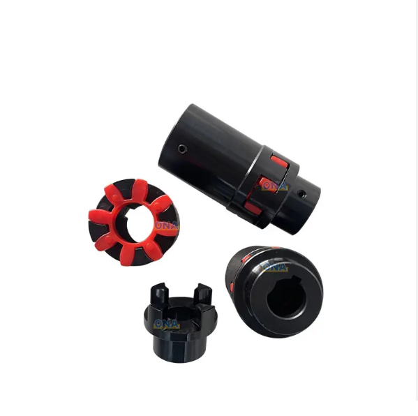
2. Composition and Structure of the Countershaft Coupling
The countershaft coupling is typically a flange-type or sleeve-type assembly, with the following key components and structural details:
Coupling Hubs: Two cylindrical hubs (input and output) with internal bores that mount to the countershaft and drive shaft. Hubs are often made of high-strength cast steel (e.g., ZG35CrMo) or forged steel, with keyways or splines for torque transmission.
Flexible Element: A component that connects the two hubs while allowing misalignment, such as:
Rubber or Elastomer Discs: Resilient discs bonded to metal plates, providing flexibility and vibration damping.
Gear Teeth: External or internal gear teeth on one hub that mesh with a corresponding gear on the other hub (gear-type coupling), allowing angular misalignment.
Pin and Bushing: Steel pins attached to one hub that fit into bushings on the other hub, with bushings made of bronze or polymer for low friction.
Flange Plates: Metal plates bolted to the hubs, securing the flexible element. Flanges are drilled with evenly spaced bolt holes for assembly, ensuring uniform load distribution.
Fasteners: High-strength bolts (e.g., 8.8 or 10.9 grade) and nuts that clamp the hubs and flexible element together, with lock washers or thread-locking adhesive to prevent loosening.
Shear Pin Holes (Optional): Radial holes for shear pins that break under excessive torque, acting as a safety mechanism to protect the drive system.
3. Casting Process for the Coupling Hubs
The coupling hubs, often large and complex in shape, are typically manufactured via casting:
Material Selection:
High-strength cast steel (ZG35CrMo) is preferred for its excellent mechanical properties: tensile strength ≥700 MPa, yield strength ≥500 MPa, and impact toughness ≥35 J/cm². It offers good castability and machinability, suitable for torque transmission.
Pattern Making:
A precision pattern is created using wood, foam, or 3D-printed resin, replicating the hub’s outer diameter, internal bore, keyway, flange, and bolt holes. Shrinkage allowances (1.5–2%) are added, with larger allowances for thick-walled sections (e.g., flange roots).
The pattern includes cores to form the internal bore and keyway, ensuring dimensional accuracy.
Molding:
A resin-bonded sand mold is prepared, with the pattern and cores positioned to form the hub’s shape. The mold cavity is coated with a refractory wash (alumina-based) to improve surface finish and prevent sand inclusion.
Melting and Pouring:
The cast steel is melted in an electric arc furnace at 1520–1560°C, with chemical composition controlled to C 0.32–0.40%, Cr 0.8–1.1%, Mo 0.15–0.25% to balance strength and toughness.
Pouring is performed at 1480–1520°C using a ladle, with a steady flow rate to avoid turbulence and ensure complete filling of the mold, especially in intricate features like keyways.
Cooling and Shakeout:
The casting is cooled in the mold for 48–72 hours to minimize thermal stress, then removed via vibration. Sand residues are cleaned using shot blasting (G25 steel grit), achieving a surface roughness of Ra25–50 μm.
Heat Treatment:
Normalization (850–900°C, air-cooled) refines the grain structure, followed by tempering (600–650°C) to reduce hardness to 180–230 HBW, improving machinability.
4. Machining and Manufacturing Process
Hub Machining:
Rough Machining: The cast hub is mounted on a CNC lathe to machine the outer diameter, flange face, and internal bore, leaving 2–3 mm finishing allowance. Keyway slots are rough-milled using a CNC milling machine.
Finish Machining: The internal bore is honed to achieve a dimensional tolerance of H7 (for clearance fit with the shaft) and surface roughness Ra0.8 μm. Keyways or splines are finish-machined to DIN 6885 standards, ensuring precise fit with shaft keys.
Flexible Element Manufacturing:
For rubber/elastomer elements: Elastomer compounds (e.g., nitrile rubber or polyurethane) are molded into discs with metal inserts, cured at 150–180°C for 10–20 minutes to achieve shore hardness 60–80 A.
For gear-type elements: Gear teeth are cut into one hub using a CNC gear hobbing machine, with a modulus of 3–8 and pressure angle 20°, ensuring compatibility with the mating hub.
Flange Plate Machining:
Flange plates are cut from steel plates (e.g., Q355B) using laser cutting, then drilled with bolt holes (positional tolerance ±0.1 mm) using a CNC drilling machine. The mating surfaces are ground to flatness (≤0.05 mm/m) for tight sealing with the hubs.
Assembly:
The flexible element is sandwiched between the two hubs, with flange plates bolted together using high-strength bolts (grade 8.8) tightened to specified torque (typically 200–500 N·m).
For shear pin designs, pins (made of 45# steel, heat-treated to HRC 30–35) are inserted into pre-drilled holes, ensuring they are the weakest link in the torque path.
Surface Treatment:
Hubs and flange plates are coated with epoxy paint or zinc plating (5–8 μm thick) to resist corrosion. Machined bore surfaces are treated with anti-seize compound to facilitate installation.
5. Quality Control Processes
Material Testing:
Chemical composition analysis (spectrometry) confirms hub materials meet standards (e.g., ZG35CrMo: C 0.32–0.40%).
Tensile testing on hub samples verifies tensile strength ≥700 MPa and elongation ≥12%.
Dimensional Accuracy Checks:
A coordinate measuring machine (CMM) inspects hub dimensions: bore diameter (H7 tolerance), keyway depth/width (±0.05 mm), and flange flatness.
Bolt hole positions are checked with a fixture gauge to ensure alignment between hubs and flanges.
Mechanical Property Testing:
Hardness testing (Brinell) ensures hub hardness is 180–230 HBW; gear teeth (if applicable) are induction-hardened to HRC 50–55, verified via Rockwell testing.
Torsional testing subjects the coupling to 120% of rated torque for 10 minutes, with no permanent deformation or cracks allowed.
Non-Destructive Testing (NDT):
Magnetic particle testing (MPT) detects surface cracks in hub keyways and flange roots, with any defect >0.3 mm in length resulting in rejection.
Ultrasonic testing (UT) inspects hub bodies for internal defects (e.g., shrinkage pores) in load-bearing regions.
Functional Testing:
Misalignment testing: The coupling is operated at rated speed with maximum allowable misalignment, with vibration levels (measured via accelerometer) limited to ≤5 mm/s.
Overload testing: For shear pin designs, the coupling is subjected to 150% of rated torque, verifying shear pins fail before hub or shaft damage occurs.
Through these processes, the countershaft coupling ensures reliable power transmission, misalignment compensation, and overload protection, contributing to the stable and efficient operation of the cone crusher in mining and aggregate processing applications