The cone crusher countershaft bushing, a critical bearing component between the countershaft and its housing, functions in load support (bearing radial and axial loads), friction reduction (minimizing energy loss at 500–1500 rpm), alignment maintenance (ensuring concentricity), and contamination protection. It requires excellent wear resistance, low friction, and dimensional stability.
Structurally, it is a cylindrical or flanged sleeve comprising a bushing body (bearing bronze like ZCuSn10Pb1, babbitt metal, or steel-backed bimetallic materials), inner bearing surface (Ra0.8–1.6 μm with oil grooves), outer surface (interference fit with housing), optional flange, lubrication features (oil grooves and holes), and optional thrust faces. Its wall thickness ranges from 5–20 mm.
For bronze bushings, the manufacturing process includes material selection, casting (centrifugal for cylindrical ones, sand casting for complex shapes), heat treatment (annealing at 500–600°C), and machining (rough and finish machining, oil groove machining). Bimetallic bushings involve steel shell preparation, bearing layer application (sintering or roll bonding), and final machining.
Quality control covers material testing (chemical composition and hardness), dimensional checks (CMM and roundness tester), microstructural analysis, performance testing (friction coefficient and wear), and fit checks. These ensure the bushing provides precision, wear resistance, and low friction for efficient power transmission in cone crushers
Detailed Introduction to the Cone Crusher Countershaft Bushing Component
1. Function and Role of the Countershaft Bushing
The cone crusher countershaft bushing (also known as the intermediate shaft bushing) is a critical bearing component mounted between the countershaft and its housing, serving as a replaceable wear part in the power transmission system. Its primary functions include:
Load Support: Bearing radial and axial loads from the countershaft, which transfers torque from the motor to the pinion gear and ultimately to the eccentric bushing.
Friction Reduction: Providing a low-friction interface between the rotating countershaft and stationary housing, minimizing energy loss and heat generation during high-speed rotation (typically 500–1500 rpm).
Alignment Maintenance: Ensuring the countershaft remains concentric with its housing, preventing misalignment that could cause excessive wear on gears and bearings.
Contamination Protection: Acting as a seal to block dust, ore particles, and moisture from entering the bearing interface, extending the service life of both the bushing and countershaft.
Given its role in high-speed, high-load operation, the countershaft bushing requires excellent wear resistance, low friction coefficient, and dimensional stability.
2. Composition and Structure of the Countershaft Bushing
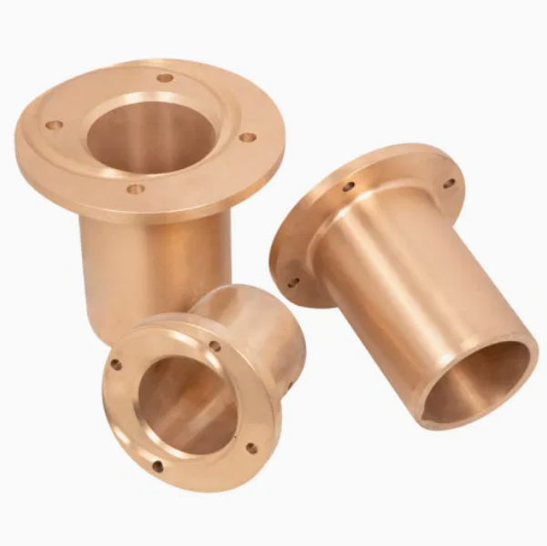
The countershaft bushing is typically a cylindrical or flanged sleeve with precise internal and external dimensions, featuring the following key components and structural details:
Bushing Body: The main cylindrical section, usually made of bearing bronze (e.g., ZCuSn10Pb1) or babbitt metal (tin-based or lead-based alloys) for their excellent anti-friction properties. Some heavy-duty designs use steel-backed bimetallic bushings (steel shell with a sintered bronze or PTFE lining).
Inner Bearing Surface: A precision-machined surface with a low roughness (Ra0.8–1.6 μm) that directly contacts the countershaft, often featuring oil grooves or pockets to retain lubricant and enhance friction reduction.
Outer Surface: A cylindrical or slightly tapered outer surface that fits into the housing bore, with an interference fit (0.01–0.05 mm) to prevent rotation relative to the housing.
Flange (Optional): A radial flange at one end to limit axial movement of the bushing in the housing and provide additional support against axial loads.
Lubrication Features:
Oil Grooves: Circumferential or axial grooves on the inner surface (0.5–2 mm deep) that distribute lubricating oil evenly across the bearing interface.
Oil Holes: Small holes (φ3–φ8 mm) connecting the outer surface to the inner grooves, allowing lubricant to flow from the housing’s oil passages into the bushing.
Thrust Faces (Optional): Machined surfaces on the bushing ends or flange to bear axial loads, often paired with thrust washers for enhanced stability.
The bushing’s wall thickness typically ranges from 5–20 mm, with larger thicknesses for heavy-duty applications to accommodate greater wear.
3. Manufacturing Process for the Countershaft Bushing
Depending on the material, countershaft bushings are manufactured using casting, sintering, or machining processes. For bronze bushings, the primary process is:
Material Selection:
Bearing bronze (ZCuSn10Pb1) is preferred for its high fatigue strength, good thermal conductivity, and compatibility with steel shafts. Its composition is controlled to Sn 9–11%, Pb 0.5–1.0%, Cu balance, ensuring a hardness of HB 80–100.
Casting:
Centrifugal Casting: For cylindrical bushings, molten bronze is poured into a rotating mold (1000–3000 rpm), creating a dense, uniform structure with fine grain size. This method ensures concentricity and reduces porosity.
Sand Casting: For flanged or complex-shaped bushings, sand molds are used, with cores to form oil holes or grooves. Pouring temperature is 1000–1100°C to ensure complete filling.
Heat Treatment:
Bronze bushings undergo annealing at 500–600°C for 1–2 hours, followed by slow cooling, to relieve casting stress and improve machinability.
Machining and Finishing:
Rough Machining: The cast blank is turned on a lathe to machine the outer diameter, inner bore, and flange (if applicable), leaving 0.5–1 mm finishing allowance.
Finish Machining: The inner and outer surfaces are precision-turned to achieve dimensional tolerances (IT6–IT7) and surface roughness Ra0.8 μm. The inner bore is honed for superior roundness (≤0.005 mm).
Oil Groove Machining: Grooves are milled or broached into the inner surface with precise depth and spacing to ensure optimal lubricant distribution.
4. Manufacturing Process for Bimetallic Bushings
For high-load applications, steel-backed bimetallic bushings are produced using:
Steel Shell Preparation: A low-carbon steel (Q235) tube or flange is drawn or machined to the desired outer dimensions, then cleaned and roughened to enhance bonding with the bearing layer.
Bearing Layer Application:
Sintering: A bronze powder (e.g., CuSn10) is sintered onto the steel shell at 800–900°C in a protective atmosphere, forming a 0.5–2 mm thick porous layer.
Roll Bonding: A thin bronze or copper sheet is rolled onto the steel shell under high pressure, creating a metallurgical bond.
Final Machining: The inner surface is machined to the required dimensions and roughness, with oil grooves added as needed.
5. Quality Control Processes
Material Testing:
Chemical composition analysis (spectrometry) verifies bronze alloys meet standards (e.g., ZCuSn10Pb1: Sn 9–11%, Pb 0.5–1.0%).
Hardness testing (Brinell) ensures bronze bushings have a hardness of HB 70–90, balancing wear resistance and ductility.
Dimensional Accuracy Checks:
A coordinate measuring machine (CMM) inspects inner and outer diameters, wall thickness uniformity, and flange thickness, with tolerances controlled to ±0.01 mm for critical dimensions.
Roundness and cylindricity of the inner surface are measured using a roundness tester, ensuring values ≤0.005 mm to prevent uneven wear.
Microstructural Analysis:
Metallographic examination checks for porosity (≤5% in bronze) and bonding quality in bimetallic bushings (no delamination between steel and bearing layers).
Performance Testing:
Friction Coefficient Testing: A tribometer measures the coefficient of friction under simulated load and speed conditions, requiring values ≤0.15 with proper lubrication.
Wear Testing: A pin-on-disk test subjects the bushing material to 10⁶ cycles, with weight loss limited to ≤5 mg to ensure long service life.
Fit and Assembly Checks:
The bushing is trial-fitted into a test housing to verify the interference fit: it should require light press force (5–20 kN) without distortion.
The inner bore is checked for compatibility with a standard countershaft sample, ensuring smooth rotation without binding.
Through these manufacturing and quality control processes, the countershaft bushing achieves the precision, wear resistance, and low friction required to ensure efficient power transmission in cone crushers, contributing to reliable operation in mining and aggregate processing applications