This paper elaborates on the drive shaft bearing of cone crushers, a key component in the transmission system that supports the drive shaft, bears loads, reduces friction, and ensures stable operation of the transmission system. It details its composition, including bearing housing, rolling elements, inner/outer rings, cage, sealing devices, and lubrication channels, along with their structural features. The casting process of the bearing housing (material selection, pattern making, melting, heat treatment, inspection), machining processes for components (rough/finish machining, heat treatment, grinding, assembly), and quality control measures (material inspection, dimensional accuracy check, surface quality inspection, performance testing, lubrication validation, final inspection) are also outlined. The drive shaft bearing's precise manufacturing and strict quality control are crucial for the efficient and reliable operation of cone crushers.
What are the precautions when you are installing the bearings of the transmission parts of the cone crusher?
1) The bearing is hot-mounted. Ensure the axial position of the bearing relative to the transmission shaft when you are installing the transmission shaft, and pad a gasket between the base and the flange of the transmission shaft frame.
2) Check the axial movement after the transmission shaft is installed, and the range of axial movement should be 0.4-0.6mm.
3) The square head fixing screws on the flange of the drive shaft frame can be used to push out during disassembling the drive shaft. Do not screw on the square head screws when the drive shaft is not removed.
4) a layer of sealant must be applied to the plane contact part and the plane of the key when you are installing the gland and the belt pulley of the main engine. Hydraulic device can be used to dismantle the main pulley.
Detailed Introduction to the Drive Shaft Bearing Component of Cone Crushers
1. Function and Significance of Drive Shaft Bearing
The drive shaft bearing is a critical component in the transmission system of cone crushers, responsible for supporting the drive shaft and ensuring its stable rotation under high-speed and heavy-load conditions. It bears radial and axial loads generated during operation, reduces friction between the drive shaft and the frame, and maintains the coaxiality of the transmission system, thereby guaranteeing the efficient and reliable operation of the crusher.
2. Composition and Structure of Drive Shaft Bearing
The drive shaft bearing assembly is composed of the following key parts, each with specific structural features:
Bearing Housing: A rigid casing that encloses and protects internal components, typically made of cast iron (HT250) or cast steel (ZG270-500). It is designed with mounting flanges or bolt holes to secure it to the crusher frame, ensuring positional stability during operation.
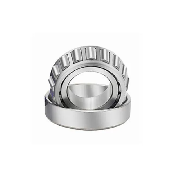
Rolling Elements: The core load-bearing components, usually consisting of tapered roller bearings (most common in cone crushers) or spherical roller bearings. Tapered roller bearings are preferred for their ability to withstand both radial and axial loads, with inner and outer rings featuring conical raceways that match the tapered rollers, enabling efficient load distribution.
Inner Ring: A ring-shaped component tightly fitted to the drive shaft, with a conical inner surface that interfaces with the shaft and a raceway for the rolling elements. Its inner diameter is precision-machined to ensure interference fit with the shaft, preventing slippage.
Outer Ring: Mounted inside the bearing housing, with a conical outer surface that fits into the housing’s tapered bore (for tapered roller bearings) or a cylindrical surface (for spherical bearings). It provides a stable raceway for the rolling elements and transfers loads to the housing.
Cage (Retainer): A structure that separates and guides the rolling elements, maintaining uniform spacing to prevent friction and collision between them. It is usually made of steel or brass, with windows or pockets to hold the rollers.
Sealing Devices: Include oil seals, O-rings, and dust covers to prevent lubricant leakage and block the entry of dust, debris, or moisture from the external environment. Lip seals are commonly used to maintain a tight seal against the rotating inner ring.
Lubrication Channels: Built into the bearing housing, these channels allow the circulation of lubricating oil or grease to reduce friction and dissipate heat, ensuring smooth operation and extending service life.
3. Casting Process for Bearing Housing (Key Component)
The bearing housing, a major cast part, undergoes the following casting process:
Material Selection: Choose HT250 gray cast iron for its good castability, machinability, and vibration damping properties, or ZG270-500 cast steel for higher strength in heavy-duty applications.
Pattern Making: Create a wooden or metal pattern based on design dimensions, with allowances for shrinkage (1-2% for cast iron) and machining. The pattern must replicate the housing’s flanges, bolt holes, and internal cavities accurately.
Molding: Use green sand or resin-bonded sand to form the mold cavity. The core (for internal cavities) is made of sand or metal, positioned to shape the bearing housing’s inner structure.
Melting and Pouring: Melt the selected material in a cupola or electric furnace (cast iron at 1350-1450°C; cast steel at 1500-1600°C). Pour the molten metal into the mold at a controlled rate to avoid turbulence and ensure complete filling.
Cooling and Shakeout: Allow the casting to cool slowly in the mold to reduce internal stress, then remove the sand mold using vibration or mechanical methods.
Heat Treatment: For cast steel housings, normalize at 850-900°C and air-cool to refine grain structure and improve toughness. Gray cast iron housings may undergo stress relief annealing at 550-600°C to reduce residual stress.
Casting Inspection: Perform visual checks for cracks, porosity, or shrinkage; use ultrasonic testing (UT) to detect internal defects; and verify dimensional accuracy with gauges.
4. Machining Process for Drive Shaft Bearing Components
Machining of Bearing Housing:
Rough Machining: Use lathes or milling machines to rough-turn the outer surface, flange faces, and bore, removing excess material and achieving basic dimensions.
Finish Machining: Precision bore the inner cavity (tapered or cylindrical) to achieve IT7-IT8 tolerance, with a surface roughness of Ra1.6-3.2μm. Machine bolt holes and flange faces to ensure flatness and perpendicularity relative to the bore axis.
Machining of Inner and Outer Rings (Rolling Bearings):
Rough Turning: Cut the forged steel blanks (high-carbon chromium steel, e.g., SUJ2/52100) into ring shapes, with rough turning of inner/outer diameters and raceways.
Heat Treatment: Quench and temper to achieve hardness of 60-64 HRC for wear resistance, followed by stress relief annealing.
Finish Grinding: Grind the raceways, inner diameter, and outer diameter to achieve high precision (IT5-IT6 tolerance) and surface finish (Ra0.4-0.8μm). Superfinish the raceways to reduce friction and noise.
Assembly:
Press-fit the inner ring onto the drive shaft using a hydraulic press to ensure proper interference fit.
Install the outer ring into the bearing housing, with shims (if needed) to adjust axial clearance for tapered roller bearings.
Insert the cage with rolling elements between the inner and outer rings, ensuring smooth movement.
Mount sealing devices and connect lubrication channels to complete the assembly.
5. Quality Control Processes
Material Inspection: Verify chemical composition (via spectrometry) and mechanical properties (tensile strength, hardness) of castings and bearing steels to meet standards.
Dimensional Accuracy: Use coordinate measuring machines (CMM) to check bearing housing bore diameter, inner/outer ring dimensions, and raceway geometry (conicity, roundness).
Surface Quality: Inspect for cracks, scratches, or unevenness using optical microscopes; measure surface roughness with a profilometer.
Performance Testing:
Rotational Test: Check for smooth rotation without noise or jamming under load.
Load Capacity Test: Subject assembled bearings to rated radial and axial loads to verify stability.
Seal Integrity Test: Conduct pressure tests with lubricant to ensure no leakage under operating conditions.
Lubrication Validation: Confirm proper lubricant flow through channels and verify that the lubricant meets viscosity and temperature resistance requirements.
Final Inspection: Each bearing assembly undergoes a comprehensive check, with test reports documenting compliance with design specifications before installation in the crusher.
In summary, the drive shaft bearing is vital for the transmission efficiency and operational safety of cone crushers. Its precise manufacturing, rigorous quality control, and robust structure ensure reliable performance under harsh working conditions