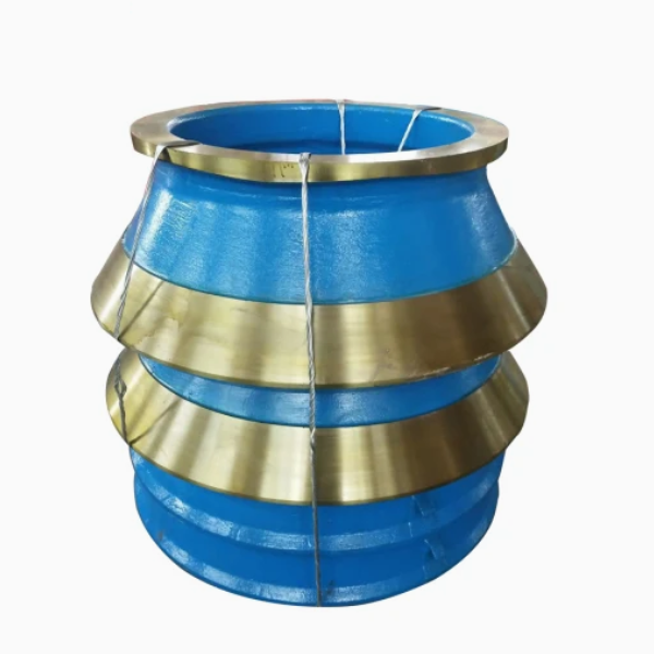
The cone crusher concave, also called the fixed cone liner or bowl liner, is a key wear-resistant component mounted on the inner surface of the bowl, forming the stationary part of the crushing chamber. Its main functions include material crushing (cooperating with the rotating mantle), wear protection (shielding the bowl), material flow guidance (via its inner profile), and product size control (influenced by inner geometry). It needs exceptional wear resistance (surface hardness ≥HRC 60), impact toughness (≥12 J/cm²), and structural integrity to withstand continuous material impact.
Structurally, it is a segmented (3–8 pieces for large crushers) or one-piece conical component. It consists of concave segments/one-piece structure, a wear-resistant body (high-chromium cast iron Cr20–Cr26 or Ni-Hard 4), an inner wear profile (tapered design with 15°–30° angle, ribs/grooves, parallel sections), mounting features (dovetail tabs, clamping holes, locating pins), outer backing (in bimetallic designs), and top/bottom flanges.
The casting process for high-chromium cast iron concaves involves material selection (Cr20Mo3 with controlled composition), pattern making (segmented patterns with shrinkage allowances), molding (resin-bonded sand mold with refractory wash), melting and pouring (induction furnace, controlled temperature and flow rate), and cooling and heat treatment (solution annealing and austempering). The machining process includes rough machining, mounting feature machining, inner profile finishing, segment assembly (for multi-piece designs), and surface treatment.
Quality control processes cover material testing (chemical composition and metallographic analysis), mechanical property testing (hardness and impact testing), dimensional accuracy checks (CMM and laser scanner), non-destructive testing (UT and MPT), and wear performance validation (accelerated testing and field trials). These ensure the concave achieves the required wear resistance, precision, and durability for efficient, long-term crushing performance in mining, quarrying, and aggregate processing
Detailed Introduction to the Cone Crusher Concave Component
1. Function and Role of the Concave
The cone crusher concave (also known as the fixed cone liner or bowl liner) is a critical wear-resistant component mounted on the inner surface of the bowl (fixed cone housing), forming the stationary part of the crushing chamber. Its primary functions include:
Material Crushing: Cooperating with the rotating mantle (moving cone liner) to apply compressive and shear forces to materials (ores, rocks), reducing them to the desired particle size through repeated squeezing and grinding.
Wear Protection: Shielding the bowl from direct contact with abrasive materials, preventing premature wear of the structural frame and reducing maintenance costs.
Material Flow Guidance: Guiding materials through the crushing chamber via its tapered or stepped inner profile, ensuring uniform distribution and progressive size reduction from the feed opening to the discharge.
Product Size Control: The concave’s inner geometry (e.g., parallel sections, curve radius) directly influences the crushing gap and particle size distribution, determining the final product quality.
Operating in high-impact, high-abrasion environments, the concave must 具备 exceptional wear resistance (surface hardness ≥HRC 60), impact toughness (≥12 J/cm²), and structural integrity to withstand continuous material impact.
2. Composition and Structure of the Concave
The concave is typically a segmented or one-piece conical component with a complex inner wear profile, consisting of the following key parts and structural details:
Concave Segments (for large crushers): Multiple arc-shaped segments (3–8 pieces) that form a complete cone when assembled, allowing easy replacement of individual worn segments. Each segment has a thickness of 50–150 mm, depending on the crusher size.
One-piece Concave (for small crushers): A single conical structure with no seams, offering higher structural rigidity for light-duty applications.
Wear-resistant Body: Made of high-chromium cast iron (Cr20–Cr26) or nickel-hard cast iron (Ni-Hard 4), with a martensitic matrix reinforced by hard chromium carbides (M7C3) to resist abrasion.
Inner Wear Profile:
Tapered Design: A cone angle of 15°–30° (matching the mantle’s taper) to create a gradually narrowing crushing chamber, ensuring progressive material reduction.
Ribs or Grooves: Transverse or longitudinal ribs (5–15 mm high) on the inner surface to enhance material gripping, prevent slippage, and promote uniform wear.
Parallel Sections: Flat segments near the discharge end to produce finer, more uniform particles by maintaining a consistent crushing gap.
Mounting Features:
Dovetail Tabs: Protrusions on the outer surface that fit into corresponding dovetail grooves in the bowl, securing the concave against rotational forces during crushing.
Clamping Holes: Bolt holes on the outer flange or edge for fastening to the bowl, preventing axial displacement under impact loads.
Locating Pins: Small protrusions or holes that align segments during assembly, ensuring a continuous inner profile with minimal gaps (≤0.5 mm between segments).
Outer Backing: A cast iron or steel reinforcement layer (in bimetallic designs) that improves impact resistance by absorbing shock, with the wear-resistant layer (high-chromium iron) cast onto the backing.
Top and Bottom Flanges: Radial edges at the feed and discharge ends that overlap with the bowl’s flanges, preventing material leakage between the concave and bowl.
3. Casting Process for the Concave
High-chromium cast iron, the primary material for concaves, is manufactured via sand casting to achieve complex wear profiles:
Material Selection:
High-chromium cast iron (Cr20Mo3) is preferred for its excellent wear resistance, with chemical composition controlled to C 2.5–3.5%, Cr 20–26%, Mo 0.5–1.0%. This forms a hard carbide network (30–40% volume fraction) in a martensitic matrix, ensuring hardness ≥HRC 60.
Pattern Making:
Segmented patterns (foam, wood, or 3D-printed resin) are created for each concave segment, replicating the inner wear profile, outer mounting features, and ribs. Shrinkage allowances (1.5–2.5%) are added to account for cooling contraction.
Molding:
A resin-bonded sand mold is prepared for each segment, with a sand core forming the inner wear profile. The mold cavity is coated with a refractory wash (alumina-based) to prevent sand inclusion and improve surface finish.
Melting and Pouring:
The cast iron is melted in an induction furnace at 1450–1500°C, with strict control of carbon equivalent (CE = C + 0.3(Si + P) ≤4.2%) to avoid shrinkage defects.
Pouring is performed at 1380–1420°C using a ladle, with a slow, steady flow rate to fill the mold cavity without turbulence, ensuring a dense structure in thin ribs.
Cooling and Heat Treatment:
The mold is cooled for 24–48 hours to reduce thermal stress, then the casting is removed via shakeout. Shot blasting (G25 steel grit) removes sand residues, achieving a surface roughness of Ra50–100 μm.
Solution Annealing: Heating to 950–1050°C for 2–4 hours, followed by air cooling to dissolve carbides and homogenize the structure.
Austempering: Quenching in oil at 250–350°C, then tempering at 200–250°C to transform the matrix into martensite, achieving hardness HRC 60–65 while maintaining toughness.
4. Machining and Manufacturing Process
Rough Machining:
Each concave segment is mounted on a CNC vertical lathe to machine the outer surface, mounting tabs, and flange edges, leaving 1–2 mm finishing allowance. Key dimensions (e.g., segment arc length, thickness) are controlled to ±0.5 mm.
Mounting Feature Machining:
Dovetail tabs are milled into the outer surface using a CNC milling machine, with dimensional tolerance (±0.1 mm) to ensure a tight fit with the bowl’s grooves.
Clamping holes are drilled and tapped to class 6H tolerance, with positional accuracy (±0.2 mm) to align with the bowl’s bolt holes.
Inner Profile Finishing:
The inner wear surface is inspected for casting defects (e.g., pores, cracks) and lightly ground to remove surface irregularities, preserving the designed profile. Surface roughness is controlled to Ra3.2 μm to optimize material flow.
For segmented concaves, the mating edges of adjacent segments are machined to ensure a gap ≤0.5 mm when assembled, preventing material leakage and uneven wear.
Segment Assembly (for multi-piece designs):
Segments are trial-fitted in a fixture to verify the inner profile continuity, with adjustments made to ensure a smooth, continuous cone surface.
Alignment pins are installed to maintain segment positions during final assembly in the crusher.
Surface Treatment:
The outer surface (mating with the bowl) is coated with anti-seize compound to facilitate installation and prevent corrosion.
The inner wear surface may undergo shot peening to induce compressive stress, reducing crack propagation under impact.
5. Quality Control Processes
Material Testing:
Chemical composition analysis (spectrometry) confirms the cast iron meets standards (e.g., Cr20Mo3: Cr 20–23%, C 2.8–3.2%).
Metallographic analysis checks carbide distribution (uniformity ≥90%) and matrix structure (martensite with ≤5% pearlite).
Mechanical Property Testing:
Hardness testing (Rockwell C) ensures the inner surface has hardness ≥HRC 60; core hardness is ≤HRC 55 to maintain toughness.
Impact testing (Charpy V-notch) measures toughness at room temperature, requiring ≥12 J/cm² to resist fracture under heavy impact.
Dimensional Accuracy Checks:
A coordinate measuring machine (CMM) inspects key dimensions: segment arc length, taper angle (±0.1°), and dovetail tab size.
A laser scanner verifies the inner profile matches the CAD model, ensuring proper alignment with the mantle to maintain the designed crushing gap.
Non-Destructive Testing (NDT):
Ultrasonic testing (UT) detects internal defects (e.g., shrinkage pores >φ3 mm) in the concave body, with critical areas (rib roots, mounting tabs) thoroughly inspected.
Magnetic particle testing (MPT) checks for surface cracks in dovetail tabs and flange edges, with any defect >0.2 mm in length resulting in rejection.
Wear Performance Validation:
Accelerated wear testing (ASTM G65) uses a dry sand/rubber wheel apparatus to measure weight loss, with high-chromium concaves requiring ≤0.5 g/1000 cycles.
Field trials involve installing the concave in a test crusher, monitoring wear rates over 500 hours of operation, ensuring uniform wear and no premature failure.
Through these manufacturing and quality control processes, the cone crusher concave achieves the wear resistance, precision, and durability required to ensure efficient, long-term crushing performance, making it suitable for mining, quarrying, and aggregate processing applications