This paper elaborates on the adjustment ring of cone crushers, a key component at the top of the fixed cone assembly that adjusts the crushing gap to control discharge material size and supports the fixed cone liner while housing safety devices. It details its composition, including the ring body, fixed cone liner mounting surface, adjustment gear teeth/threads, hydraulic cylinder ports/spring chambers, lubrication channels, sealing grooves, and locking mechanism, along with their structural features. The casting process for the ring body is outlined, covering material selection, pattern making, molding, melting, pouring, heat treatment, and inspection. It also describes machining and manufacturing processes (rough machining, stress relief annealing, finish machining, surface treatment, assembly) and quality control measures (material validation, dimensional accuracy checks, functional testing, wear resistance testing, final inspection). These processes ensure the adjustment ring provides accurate gap adjustment and reliable protection for cone crushers in demanding applications.
Detailed Introduction to the Cone Crusher Adjustment Ring Component
1. Function and Role of the Adjustment Ring
The adjustment ring (also known as the bowl ring or regulating ring) is a key component in cone crushers, located at the top of the fixed cone assembly. Its primary function is to adjust the crushing gap between the moving cone (head) and the fixed cone (bowl liner), thereby controlling the size of the discharged material. By rotating the adjustment ring, the fixed cone moves up or down, altering the gap width to adapt to different material hardness and desired product granularity. Additionally, it serves as a structural support for the fixed cone liner and houses safety devices (e.g., hydraulic cylinders or springs) that protect the crusher from overloads by allowing temporary upward movement during unexpected impacts.
2. Composition and Structure of the Adjustment Ring
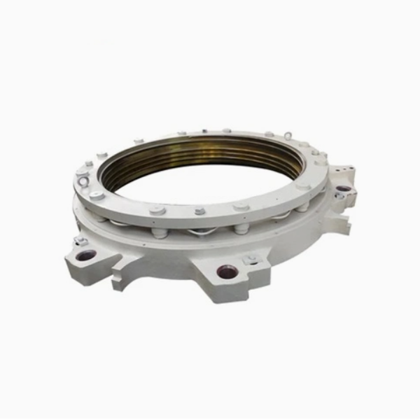
The adjustment ring is a large, annular component with a robust design, consisting of the following core parts:
Ring Body: The main annular structure, typically made of high-strength cast steel (ZG35CrMo) or ductile iron (QT500-7), with an outer diameter ranging from 1 to 5 meters depending on the crusher size. Its inner surface features threads or gear teeth that mesh with the adjustment mechanism (e.g., hydraulic motors or manual handles) to facilitate rotation.
Fixed Cone Liner Mounting Surface: A tapered or stepped inner surface on the ring body that secures the fixed cone liner (bowl liner) via bolts, dovetail grooves, or wedge clamps. This surface is precision-machined to ensure a tight fit, preventing liner movement during crushing.
Adjustment Gear Teeth or Threads: External or internal gear teeth (modulus 8–12) or trapezoidal threads on the ring body, which engage with the drive pinion or adjustment nut to transmit rotational force for gap adjustment.
Hydraulic Cylinder Ports or Spring Chambers: Recesses or bores in the ring body that house hydraulic cylinders (for hydraulic adjustment systems) or compression springs (for mechanical systems). These components absorb overload forces and reset the ring to its original position after a jam.
Lubrication Channels: Drilled holes or grooves that deliver lubricant to the gear teeth, threads, and mounting surfaces, reducing friction and wear during rotation and operation.
Sealing Grooves: Circumferential grooves on mating surfaces (e.g., between the ring and crusher frame) that hold O-rings or gaskets to prevent dust ingress and lubricant leakage.
Locking Mechanism: A set of bolts, pawls, or hydraulic clamps that secure the adjustment ring in place after setting the desired gap, preventing unintended rotation during crushing.
3. Casting Process for the Ring Body
The adjustment ring body is manufactured using sand casting or investment casting, with the following steps:
Material Selection:
Cast steel (ZG35CrMo) is preferred for large crushers due to its high tensile strength (≥785 MPa) and impact toughness, suitable for withstanding heavy loads and dynamic stresses.
Ductile iron (QT500-7) is used for medium-sized rings, offering better castability and lower cost while maintaining sufficient strength (tensile strength ≥500 MPa).
Pattern Making:
A full-scale pattern is created using foam, wood, or 3D-printed materials, replicating the ring’s outer diameter, inner threads/teeth, and internal features. For large rings, segmented patterns are used to simplify handling.
Shrinkage allowances (2–3% for cast steel) and draft angles (3–5°) are added to compensate for post-casting contraction.
Molding:
Resin-bonded sand molds are formed around the pattern, with sand cores used to create internal cavities (e.g., cylinder ports). The mold is reinforced with steel rods to prevent deformation during pouring.
For investment casting (used for complex gear teeth), a ceramic shell is formed by dipping the foam pattern in refractory slurry, followed by drying and sintering.
Melting and Pouring:
Cast steel is melted in an electric arc furnace at 1520–1580°C, with alloying elements (Cr, Mo) added to achieve the desired chemical composition. The molten metal is treated to reduce sulfur and phosphorus content (≤0.03%).
Pouring is performed in a single stream at a controlled rate (100–300 kg/s) to ensure complete mold filling and minimize turbulence, which can cause porosity.
Cooling and Shakeout:
The casting is allowed to cool slowly in the mold for 48–72 hours to avoid thermal cracking, then removed via vibration or crane. Sand residues are cleaned using shot blasting or high-pressure water jets.
Heat Treatment:
Cast steel rings undergo normalization (860–900°C, air-cooled) to refine grain structure, followed by tempering (600–650°C) to achieve a hardness of 220–260 HBW, balancing strength and machinability.
Ductile iron rings are annealed (900–950°C) to eliminate carbides and improve ductility.
Casting Inspection:
Visual inspection and dye penetrant testing (DPT) check for surface cracks, blowholes, or incomplete gear teeth.
Ultrasonic testing (UT) and radiographic testing (RT) detect internal defects, with strict limits (no defects >φ5 mm in the ring body or gear teeth).
4. Machining and Manufacturing Process
Rough Machining:
The outer and inner surfaces of the ring are turned on a large CNC lathe to remove excess material, leaving 3–5 mm finishing allowance. Gear teeth or threads are rough-cut using a hobbing machine or thread mill.
Hydraulic cylinder ports and bolt holes are drilled and countersunk to approximate dimensions.
Stress Relief Annealing:
After rough machining, the ring is heated to 550–600°C for 4–6 hours and slowly cooled to eliminate residual stresses from casting and initial cutting, preventing distortion during finish machining.
Finish Machining:
The inner mounting surface for the fixed cone liner is precision-ground to a taper tolerance of ±0.05 mm/m and surface roughness Ra1.6–3.2 μm, ensuring a tight liner fit.
Gear teeth are finish-hobbed or ground to AGMA 8–10 accuracy, with tooth profile deviations ≤0.03 mm to ensure smooth meshing with the drive pinion.
Threads are precision-turned or ground to ISO 286 tolerance class 6H, with flank surface roughness Ra3.2 μm for reliable engagement.
Hydraulic ports are honed to ensure concentricity with the cylinder bores, and sealing grooves are machined to exact dimensions (width ±0.02 mm, depth ±0.01 mm).
Surface Treatment:
The outer surface is painted with an anti-corrosive primer and topcoat (dry film thickness ≥120 μm) to resist environmental damage.
Gear teeth or threads are coated with molybdenum disulfide or phosphate to reduce friction and enhance wear resistance.
Assembly:
Hydraulic cylinders or springs are installed into their respective chambers, with seals and O-rings fitted to prevent leakage.
The locking mechanism (bolts or clamps) is mounted, and functional tests are performed to verify smooth rotation and secure locking.
5. Quality Control Processes
Material Validation:
Spectrometric analysis confirms the chemical composition of cast steel/iron (e.g., ZG35CrMo: C 0.32–0.40%, Cr 0.8–1.1%, Mo 0.15–0.25%).
Tensile tests on coupons from each casting batch ensure mechanical properties meet standards (tensile strength, impact toughness).
Dimensional Accuracy Checks:
Coordinate measuring machines (CMM) with a measuring range of ≥6 meters verify key dimensions, including outer diameter, inner taper, gear tooth pitch, and thread lead.
A gear rolling tester checks tooth contact patterns and backlash (0.1–0.3 mm) to ensure smooth meshing.
Functional Testing:
Rotation test: The ring is rotated through 360° under load to ensure no binding, with torque measurements confirming smooth operation (≤5% variation from design specs).
Hydraulic system test: For hydraulic rings, pressure testing at 1.5× rated pressure (e.g., 30 MPa) for 1 hour ensures no leaks from cylinder ports or seals.
Wear Resistance Testing:
Gear teeth undergo a 10,000-cycle wear test under simulated load, with wear depth ≤0.1 mm acceptable.
Threaded surfaces are tested for galling resistance under repeated assembly/disassembly cycles.
Final Inspection:
A comprehensive review of all test reports, including material certificates, NDT results, and dimensional records, is conducted before certification.
The ring is trial-fitted with the fixed cone liner and adjustment mechanism to confirm compatibility and proper alignment.
By following these rigorous processes, the adjustment ring achieves the required strength, precision, and durability, ensuring accurate gap adjustment and reliable protection for the cone crusher in demanding mining and aggregate applications