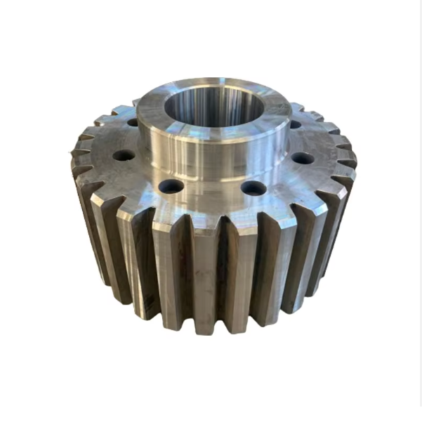
The cone crusher adjustment gear, a key part of the gap adjustment system, modifies the crushing gap between mantle and concave to control product size. Its functions include gap adjustment (converting rotation to vertical bowl movement), torque transmission, locking adjusted positions, and load distribution, requiring high strength and precise tooth geometry.
Structurally, it is a ring-shaped component with a gear ring body (high-strength cast steel ZG42CrMo), external/internal teeth (module 8–20), mounting flange, optional threaded interface, lubrication channels, and locking features.
Manufacturing involves sand casting (material selection, pattern making, molding, melting/pouring, heat treatment), machining (rough machining, tooth machining, thread/flange processing, drilling lubrication channels), and surface treatment (tooth carburizing, epoxy coating).
Quality control includes material testing (composition, tensile strength), dimensional checks (CMM, gear measuring center), structural testing (UT, MPT), mechanical performance testing (hardness, load tests), and functional testing. These ensure reliable, precise gap adjustments for consistent cone crusher operation
Detailed Introduction to the Cone Crusher Adjustment Gear Component
1. Function and Role of the Adjustment Gear
The cone crusher adjustment gear (also called the adjusting ring gear or eccentric adjustment gear) is a critical component in the crusher’s gap adjustment system, responsible for modifying the crushing gap between the mantle and concave to control product size. Its primary functions include:
Gap Adjustment: Translating rotational motion into vertical movement of the bowl (or concave), allowing operators to increase or decrease the crushing gap to achieve the desired particle size.
Torque Transmission: Transferring power from the adjustment drive motor (via a pinion or hydraulic system) to the bowl, enabling precise positioning even under heavy loads.
Locking Mechanism: Engaging with locking devices (e.g., hydraulic clamps or locknuts) to secure the adjusted position, preventing unintended movement during crushing.
Load Distribution: Distributing axial loads from the bowl to the frame during adjustment and operation, ensuring stability and reducing wear on mating components.
Operating in a high-torque, dusty environment, the adjustment gear requires high strength, wear resistance, and precision tooth geometry to ensure smooth, reliable gap adjustment.
2. Composition and Structure of the Adjustment Gear
The adjustment gear is typically a large, ring-shaped component with external or internal teeth, featuring the following key parts and structural details:
Gear Ring Body: A heavy-duty ring made of high-strength cast steel (e.g., ZG42CrMo) or forged steel, with an outer diameter ranging from 500 mm to 3000 mm depending on crusher size. The body thickness is 80–200 mm to withstand axial loads.
Tooth Profile:
External Teeth: Most common design, with trapezoidal or involute teeth (module 8–20) machined on the outer circumference, engaging with a smaller pinion gear from the adjustment drive.
Internal Teeth: Used in some designs, with teeth on the inner circumference to save space, mating with a central drive gear.
Mounting Flange: A radial flange on the bottom or top of the gear ring, featuring bolt holes to connect to the bowl or adjustment ring. The flange ensures concentricity between the gear and bowl.
Threaded Interface (Optional): A trapezoidal thread on the inner surface that engages with a corresponding thread on the frame, converting rotational motion into vertical movement of the bowl.
Lubrication Channels: Radial or axial holes delivering lubricant to tooth surfaces and threaded interfaces, reducing friction and preventing galling.
Locking Features:
Clamp Grooves: Circumferential grooves on the outer surface for hydraulic clamp pistons to lock the gear in position.
Notches or Holes: For mechanical locking pins that secure the adjusted position during maintenance.
3. Casting Process for the Adjustment Gear
Given its large size and complex shape, the adjustment gear is primarily manufactured via sand casting:
Material Selection:
High-strength cast steel (ZG42CrMo) is preferred for its excellent tensile strength (≥750 MPa), impact toughness (≥30 J/cm²), and wear resistance. Chemical composition is controlled to C 0.38–0.45%, Cr 0.9–1.2%, Mo 0.15–0.25% to balance strength and machinability.
Pattern Making:
A full-scale pattern (foam, wood, or 3D-printed resin) is created, replicating the gear ring’s outer diameter, flange, bolt holes, and tooth profiles (simplified for casting). Shrinkage allowances (1.5–2.5%) are added, with larger allowances for thick sections.
Molding:
A resin-bonded sand mold is prepared, with the pattern positioned to form the gear’s outer surface and flange. Cores are used to create the inner bore and bolt holes, ensuring wall thickness uniformity (tolerance ±3 mm).
Melting and Pouring:
The cast steel is melted in an electric arc furnace at 1520–1560°C, with strict control of sulfur and phosphorus content (≤0.035% each) to avoid brittleness.
Pouring is performed at 1480–1520°C using a ladle, with a controlled flow rate (50–100 kg/s) to fill the mold cavity without turbulence, minimizing porosity in the gear teeth.
Heat Treatment:
Normalization: Heating to 850–900°C for 4–6 hours, followed by air cooling to refine the grain structure and reduce internal stress.
Tempering: Heating to 600–650°C for 3–5 hours to reduce hardness to 180–230 HBW, improving machinability while maintaining strength.
4. Machining and Manufacturing Process
Rough Machining:
The cast gear ring is mounted on a CNC vertical lathe to machine the outer diameter, inner bore, and flange, leaving 5–10 mm finishing allowance. Key dimensions (e.g., flange flatness) are controlled to ±1 mm.
Tooth Machining:
Rough Cutting: Teeth are rough-machined using a CNC gear hobbing machine, removing excess material while following the involute or trapezoidal profile. For large gears, a gear shaper may be used for internal teeth.
Finish Grinding: Teeth are precision-ground using a gear grinder to achieve accurate tooth profile (tolerance ISO 8–10), pitch (±0.05 mm), and surface roughness (Ra1.6 μm) for smooth meshing.
Thread and Flange Machining:
Trapezoidal threads (if present) are cut using a CNC thread milling machine, with pitch and lead accuracy (±0.1 mm) to ensure smooth vertical movement.
The mounting flange is finish-machined to flatness (≤0.05 mm/m) and perpendicularity to the gear axis (≤0.1 mm/100 mm) using a CNC grinder. Bolt holes are drilled and tapped to class 6H tolerance.
Lubrication Channel Drilling:
Axial and radial oil holes (φ5–φ10 mm) are drilled using CNC deep-hole drilling machines, with positional accuracy (±0.2 mm) to ensure lubricant reaches tooth roots and threaded surfaces.
Surface Treatment:
Tooth surfaces are carburized and quenched to a depth of 1–2 mm, achieving hardness HRC 58–62 to enhance wear resistance.
Non-tooth surfaces are coated with epoxy paint (100–150 μm thick) to resist corrosion in mining environments.
5. Quality Control Processes
Material Testing:
Chemical composition analysis (spectrometry) confirms compliance with ZG42CrMo standards (C 0.38–0.45%, Cr 0.9–1.2%).
Tensile testing on cast samples verifies tensile strength ≥750 MPa and elongation ≥12%.
Dimensional Accuracy Checks:
A coordinate measuring machine (CMM) inspects gear dimensions: outer diameter (±0.5 mm), tooth pitch, and thread parameters.
A gear measuring center verifies tooth profile, helix angle, and pitch deviation, ensuring compliance with ISO 8 standards.
Structural Integrity Testing:
Ultrasonic testing (UT) detects internal defects in the gear body and flange, with any shrinkage pores >φ5 mm rejected.
Magnetic particle testing (MPT) checks for surface cracks in tooth roots, bolt holes, and thread roots, with linear defects >1 mm resulting in rejection.
Mechanical Performance Testing:
Hardness testing (Rockwell) ensures tooth surfaces have HRC 58–62 and the core has 180–230 HBW.
Load testing involves applying 120% of rated torque via a hydraulic gear tester, with no tooth deformation or cracking allowed.
Functional Testing:
A trial assembly with the bowl and adjustment drive verifies smooth rotation: the gear meshes with the pinion without binding, and the bowl moves vertically uniformly.
Locking mechanisms are tested to ensure they hold the adjusted position under 150% of operating load.
Through these manufacturing and quality control processes, the adjustment gear achieves the precision, strength, and reliability required to enable accurate, repeatable crushing gap adjustments, ensuring consistent product size and efficient operation in cone crushers for mining and aggregate processing